QuickCAST Flow Simulation


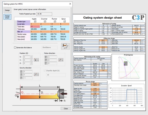
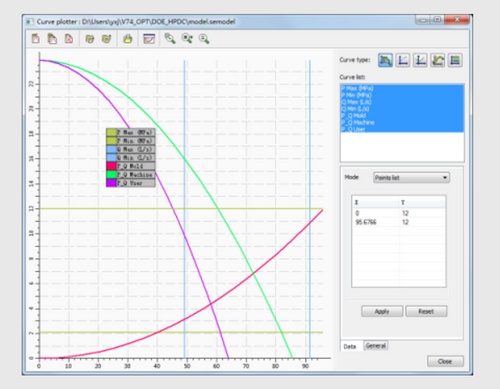
The HPDC Gating Design Wizard simplifies gating design by allowing users to input casting details like weight, projected area, material, shot machine, and biscuit size. It generates a PQ graph to verify the shot machine's capability, and provides key results like filling time, ingate velocity, required ingate area, and phase velocities and shift times. The wizard also calculates casting pressure, clamping force margins, and runner cross-sections for use in Smart Runner Design. This streamlined process ensures an efficient, accurate, and quick gating design, reducing the time and effort required for setup.
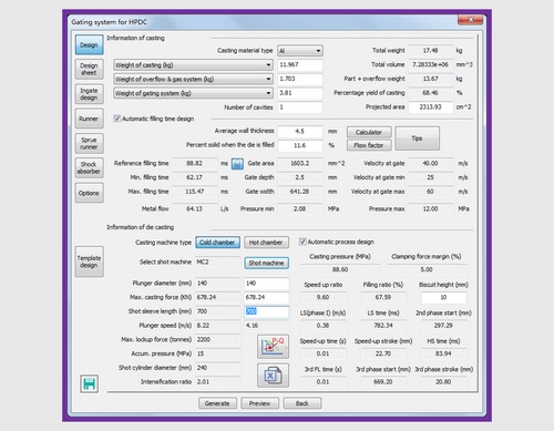
These tools help designers quickly calculate different aspects of HPDC gating design:
Choosing the correct part orientation and selecting ingate locations are critical tasks in gating system design, especially during new product development. These decisions require skill and experience, often involving multiple iterations and significant time and cost in flow simulations or trial die designs.
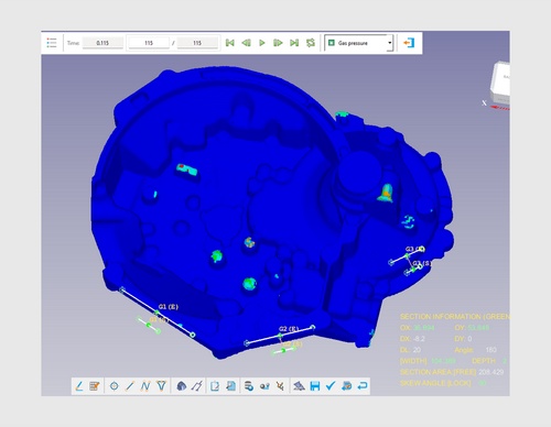
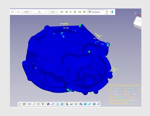
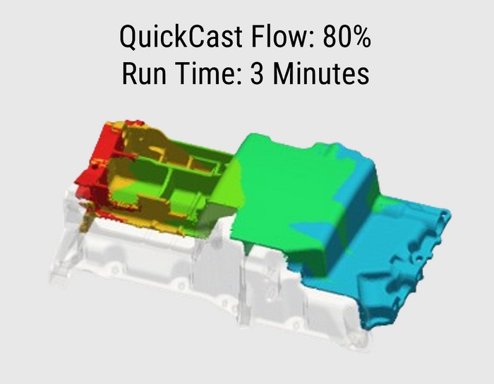
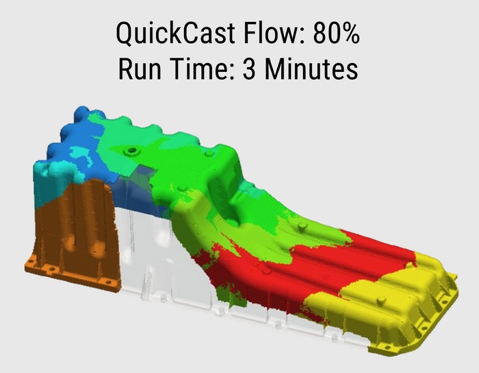
QuickCAST, part of the Cast-Designer suite, provides metal flow simulations in just a few minutes.
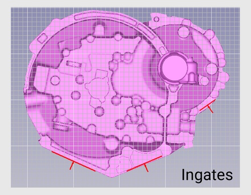
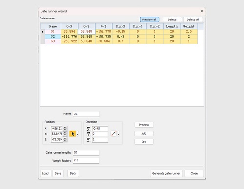
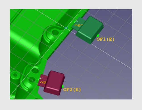
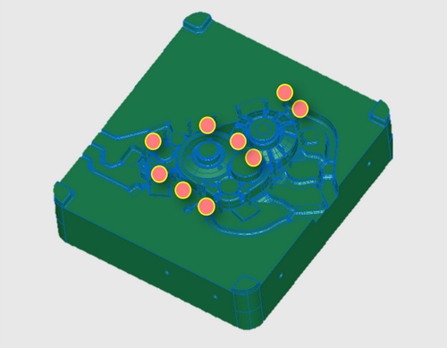
To create an ingate, simply define:
You can define as many ingates as needed. This is sufficient for flow simulation in QuickCast. Once set, users can easily visualize the flow pattern through these ingates.
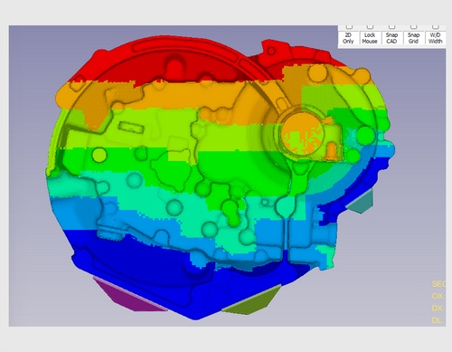
It delivers key results, including:
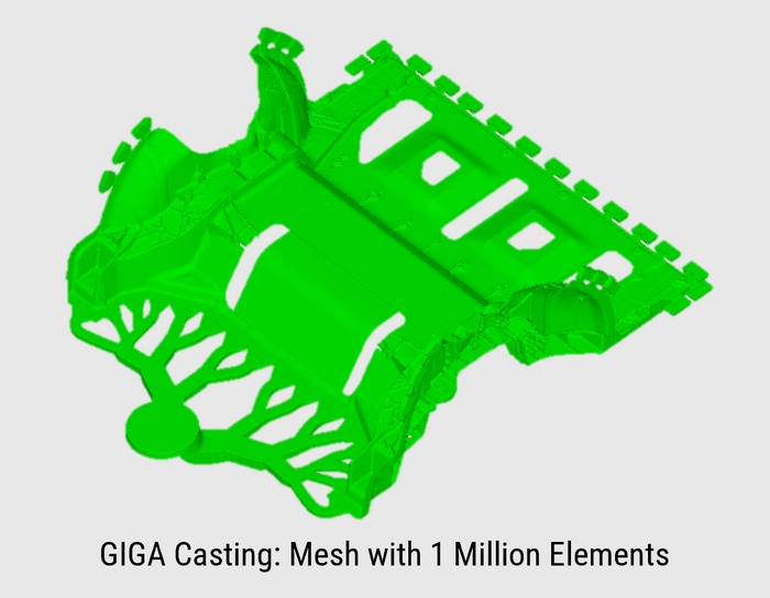
Simulations for a 1-million mesh model take less than 5 minutes, saving engineers valuable time.
The fast and insightful results enable engineers to experiment with different gating methods and ingate locations, optimizing the filling process without the need for numerous full-scale flow simulations. This reduces the number of iterations required, ultimately saving time and costs.
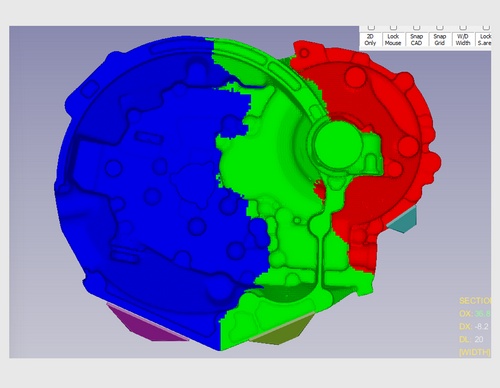
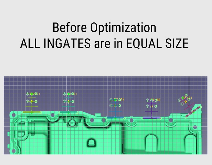
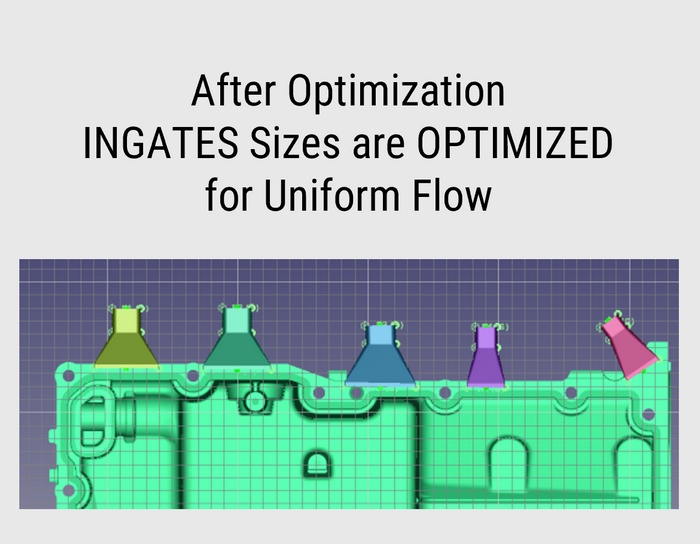
The QuickCAST Optimization Tool allows casting designers to fine-tune ingate locations and sizes to achieve optimal results, such as balancing the flow of liquid metal within the casting.
Two methods are available: DOE (Design of Experiments) manual, or automatic. The tool runs multiple iterations of QuickCAST flow simulations until the desired result is achieved.
Users can set guidelines for ingate adjustments, including minimum and maximum sizes, flow volume, and flow length as criteria for optimization.
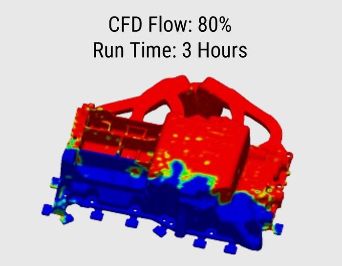
QuickCAST delivers results in just a few minutes by considering only the geometry of the casting. The results are 80% to 90% comparable to those of full-scale CFD flow simulations.
Use it during initial design stage iterations
CFD simulations take hours to produce accurate flow results by accounting for factors such as temperature, velocity, surface tension, viscosity, and friction. While more accurate and realistic, CFD is typically used for final evaluation of gating for flow results.

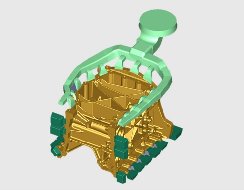
SmartRunner is a breakthrough self-learning AI technology in Cast-Designer. With Smart runner, the system can generate the gating system in a semi-automatic way. The user only needs define the biscuit size and position, also provides the guideline link information, then the system will generate the gating system automatically.
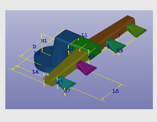
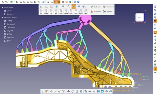
After completing Gating wizard page and ingate design, now it's time to create runners. Ingate locations and sizes are already defined and optimized, now just add sprue/biscuit location and connect ingates to the sprue/biscuit through smart runners. Smart runner gating design tools has intelligence about the standard definition of different runner shapes.
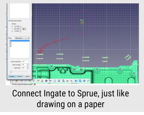
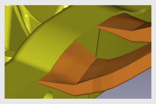
Place Sprue. To create runner, select an ingate (created in previous step) and pick a point towards sprue, runner automatically created as per width of the ingate size.
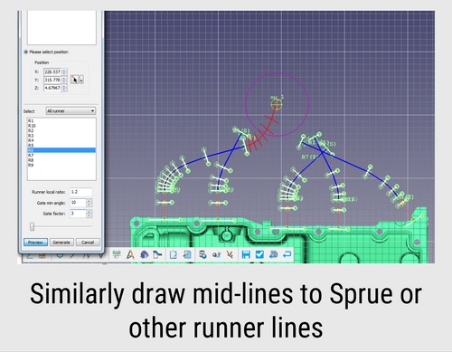
Select other ingates and points of the desired location of the runner on screen, runner automatically created with correct width, draft, height as required for the ingate.
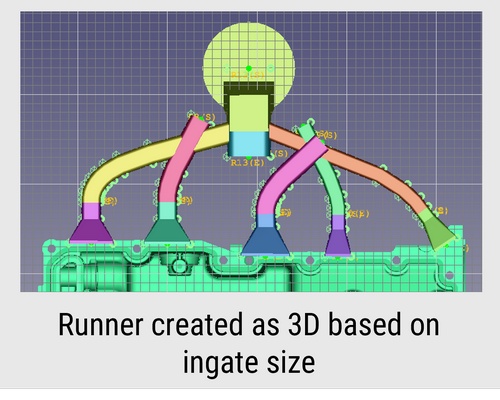
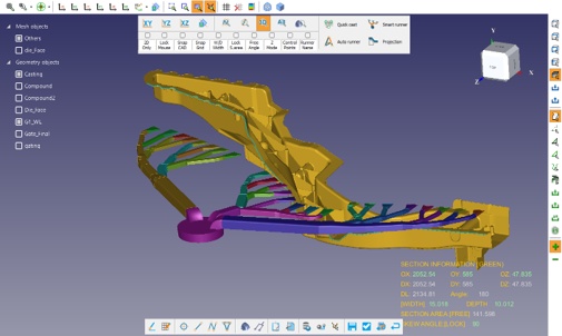
View runners in 3D, runner section width and height gradually reduced with proper draft angle. Each runner width is as per the width required for the ingate.
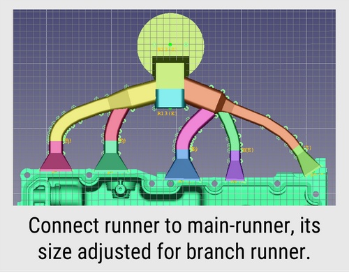
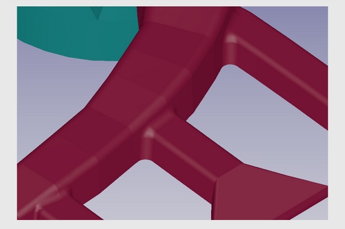
Select 1st runner as master and select 2nd to merge, runner section of the 1st runner automatically adjusted where 2nd runner is merging. Similarly in the other side runners.
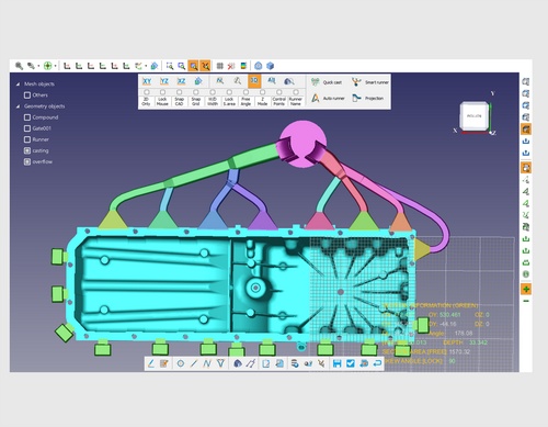
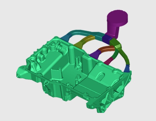
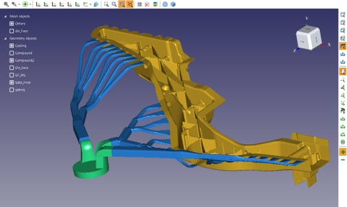
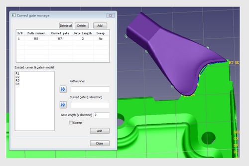
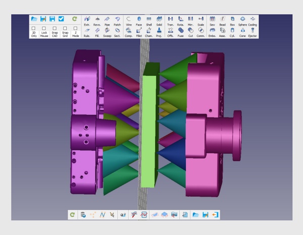
Even if for complex 3D runner system, the Cast-Designer system can handle it easily. Define the workspace and create the 3D die face and addendum in ParaCAD, the build-in CAD system. Using 3D runner projection function to get the CAD based 3D runner system.
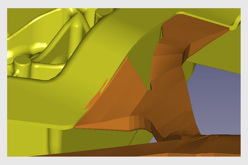
Features like inner gates also modified to match the parting line surface
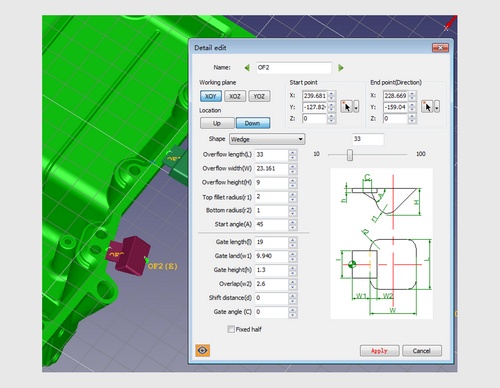
Adjust the overflow size by simple parameter and fully linked.
Flexible display and hidden/show button.
What You See What You Get style design.
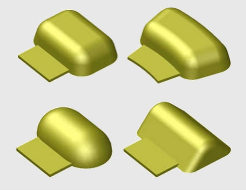
Complex overflow shape creation capabilities.
Overflow could be designed in free style method, flexible operation and easy location.
Easy to copy the properties of overflow.
Detail modification for overflow, fully parametric.
Support user's database of preferred configurations.
Build-in pre-defined overflow type and parametric.
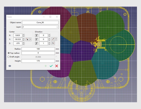
And the venting block design, could be done in full parametric, also to support vacuum system.
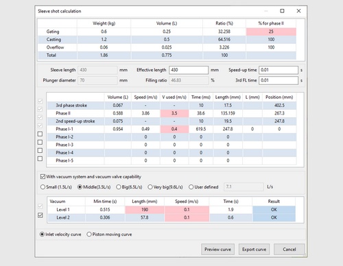
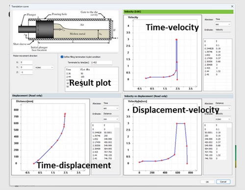
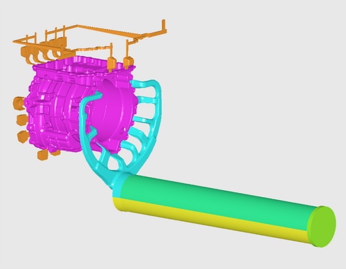
Include Shot Sleeve into your simulation model
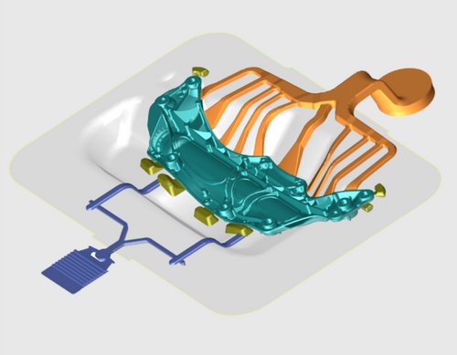
The cooling system is key to controlling solidification, reducing shrinkage porosity, and minimizing stress and distortion in your castings. A well-designed cooling system directly impacts die life and production rates.
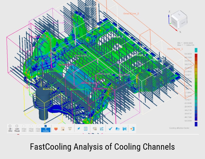
Cast-Designer introduces a revolutionary approach to cooling system design and analysis, SmartCooling Design and FastCooling Analysis to quickly assess design performance.
In traditional casting simulation, die thermal balance is analyzed and optimized through a complex and time-consuming Full-Mould Cyclic Flow and Solidification Simulation, which requires:
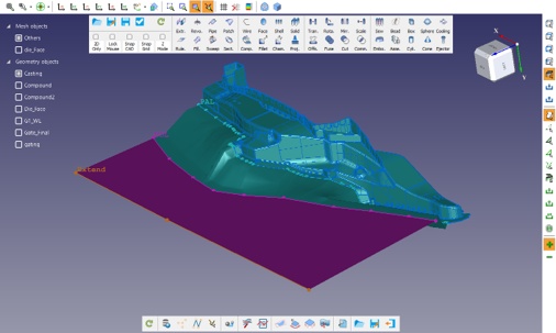
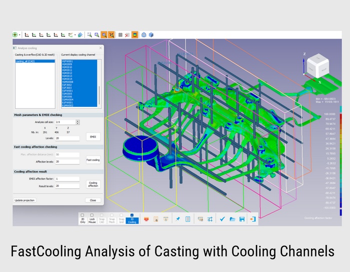
During the design stage, engineers can use Cast-Designer's Fast Cooling Feature. This geometry-based mass-thermal cooling analyzer simplifies the process by:
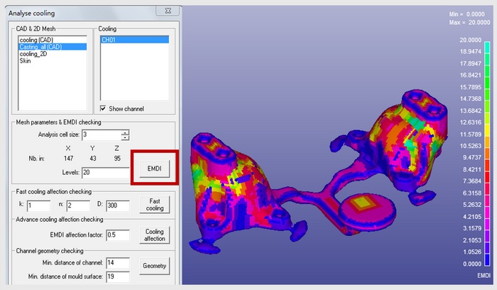
EMDI: Extracts the Mass Distribution Index of the part
EMDI thickness is mapped on the 3D part surface and displayed in a color contour.
The system will generate a smooth background mesh automatically.
A smaller cell size can get more accurate result but need more CPU time and resources for display.
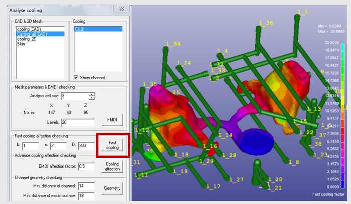
Cooling Affection: Select the cooling channels for analysis
Run the fast cooling analysis – takes 3 minutes
Fast Cooling analysis considers the heat affection of the channels to the SURFACE of casting part using inverse method
Displays results in color contour
The cooling affection formula could be customized
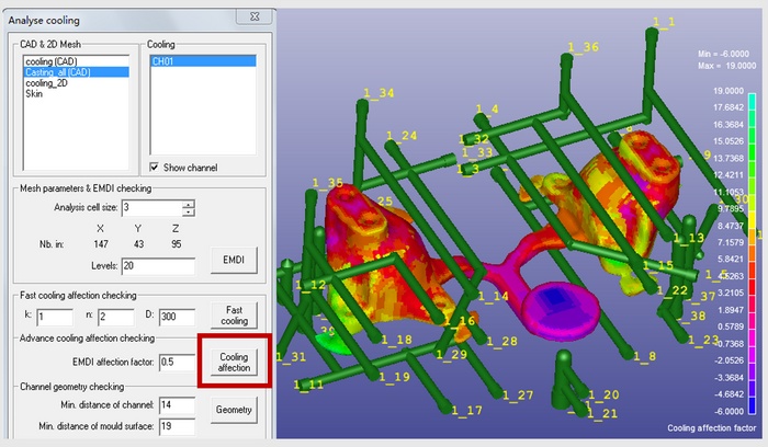
Fast Cooling Analysis on EMDI & Cooling Affection on the Casting part: Combine both the EMDI and fast cooling result together to get the cooling affection result.
Now, cooling affection with respect to mass of the component is displayed in color contour, which is more accurate than surface level analysis.
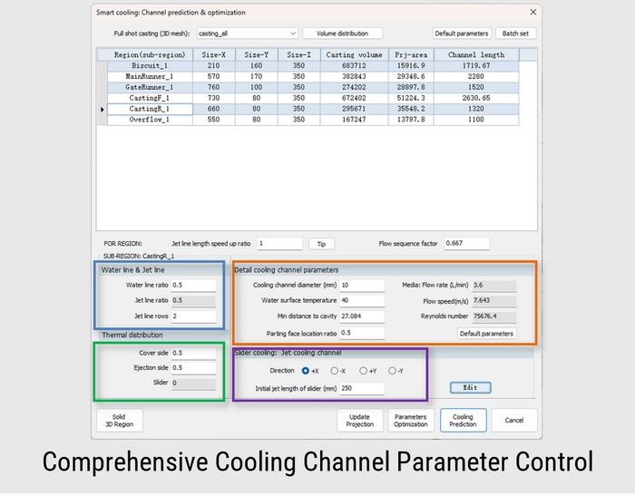
SmartCooling automates the critical die casting cooling design process using a 3-step approach that ensures a comprehensive and optimized cooling system. This method accelerates the cooling design process, increasing speed by 10 to 30 times.
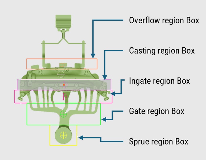
Based on the metal flow path, the system or user assigns regions to the casting system, supporting up to six main regions and 24 sub-regions.
The casting volume and projection area are distributed across these sub-regions.
Users input the casting and mold material, production rate, and cooling channel properties to complete the setup.
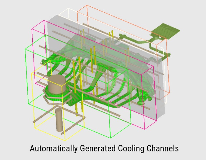
By assigning different cooling channel properties, such as standard or jet cooling.
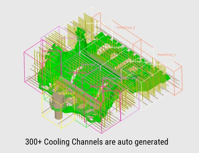
The system predicts the optimal cooling system and automatically generates a fully parametric cooling channel geometry and layout design.
This is the core technology behind SmartCooling intelligence.
Check the effectiveness of the cooling channel design using the FastCooling Analysis feature.
Users can make modifications to the cooling channel design, and any adjustments to location or cooling power will be immediately reflected in the FastCooling analysis, providing real-time feedback.
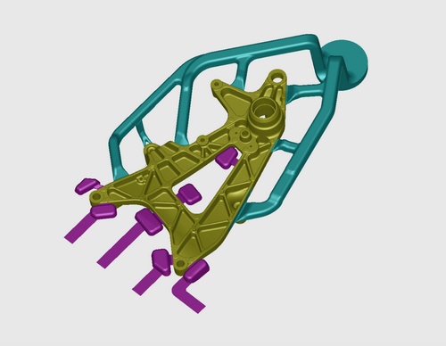
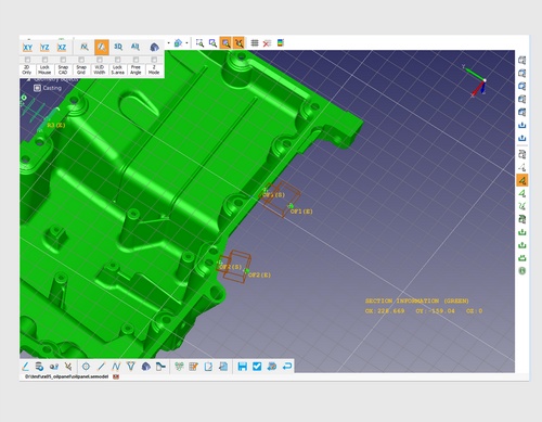
Cooling design for Giga is time consuming and huge numbers of cooling difficult to manage because of its large numbers, Cast-Designer provides complete tools to auto create, manual adjustment, group wise management.
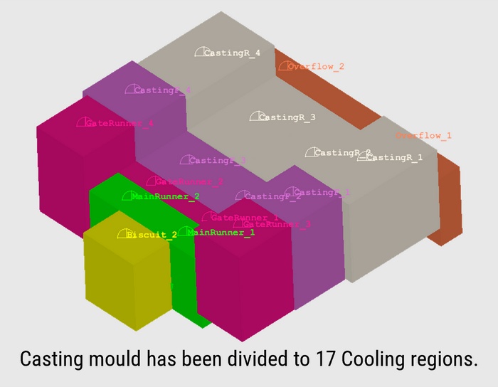
Considering the geometry properties, the casting mould has been divided to 17 regions. The cooling channel in each region could be designed separately.
Predicted cooling system based on the casting geometry and the thermal balance, the parameters of each sub-region was optimized.
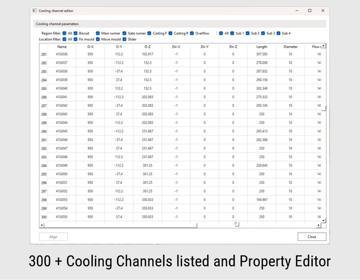
All parameters listed in a datasheet with Excel-like editing capabilities including center coordinates, line direction, length, diameter, and flow rate.
Region, sub-region, and location filters help quickly find related cooling channels.
Align function enables batch property editing. Batch rename maintains naming consistency after modifications.
Mirror channels to opposite mold halves and update projections after adjustments.
Contour displays show X/Y/Z coordinates to verify channel locations.
Generate cooling channels and region boxes directly to CAD environment.
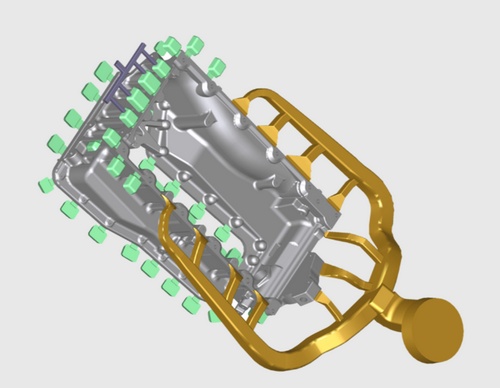
Die-spray is a critical yet often overlooked process in die casting. Improper or uneven die-spray can cause rapid cooling that affect casting quality, and mainly damages delicate die areas, which may result in frequent repairs, maintenance, or replacement — ultimately halting production.
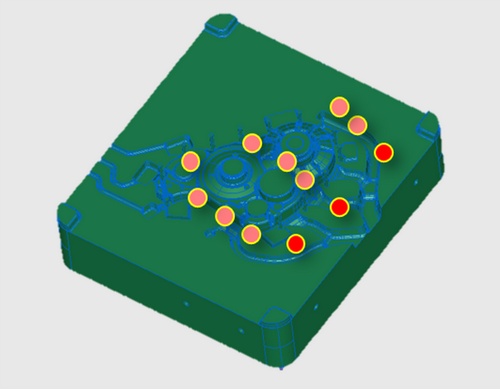
Cast-Designer's advanced die-spray model enables users to simulate every aspect of die preparation. This includes considering the mold surface shape, die temperature, as well as the position and movement of spray nozzles, open and close time of different spray nozzles. It ensures optimal cooling distribution and prolongs die life while maintaining production efficiency.
The dynamic heat transfer coefficient (HTC) derived from this simulation can be used in the most accurate Full-Mould Cyclic Flow-Solidification Simulation, enhancing the overall simulation precision.
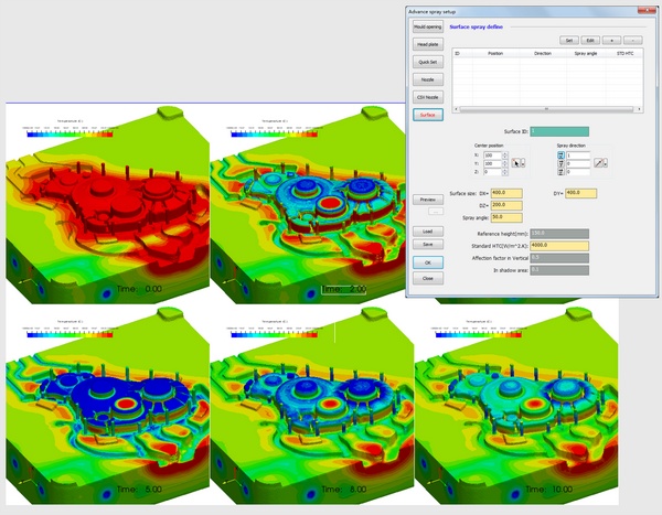
Surface style spraying is a quick and simplified method for spraying simulation. It’s useful for initial simulations to reduce the time needed for detailed spray modeling, while still providing reasonably accurate results.
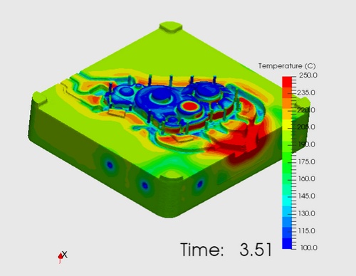
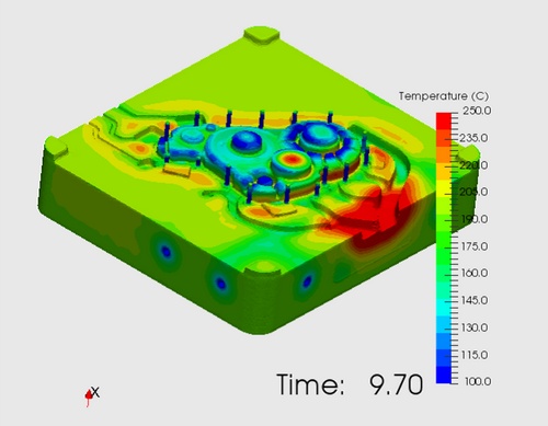
There are two design plans for advance spraying. One is no nozzles on the main runner region and another one was three nozzles on the main runner region. The lead time of spraying was 5 seconds only and the whole simulation was 10 seconds.
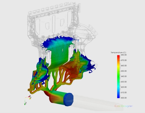
The result of 4.51 second shows the different of temperature distribution of the vertical region and this affection is continue until the end of the simulation.
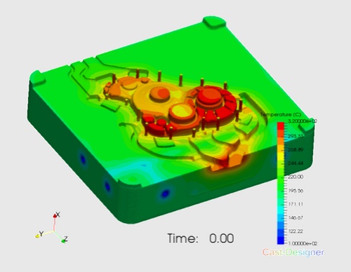
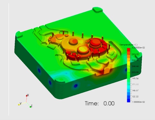
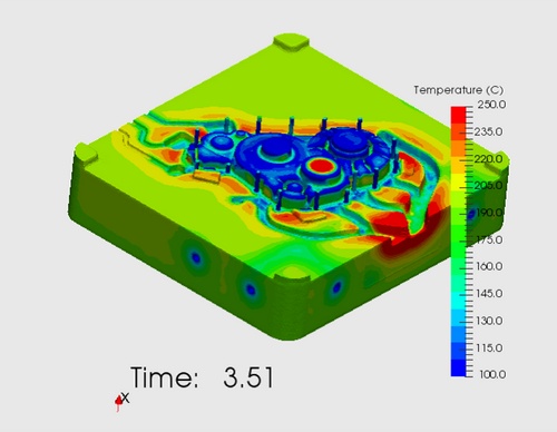
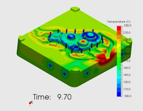
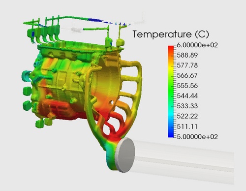
Temperature distribution on the die surface during the complete casting cycle
In complex cooling systems, media flow within the channels can be quite intricate. Performing a thermal and flow simulation provides a detailed examination of both the media flow and temperature distribution. Furthermore, the dynamic heat transfer coefficient (HTC) can be derived from the results of the simulation, which can be used in the most accurate Full-Mould Cyclic Flow-Solidification Simulation.
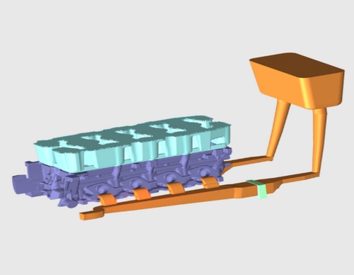
The quality of parts produced by die casting may be affected during the ejection stage of the molding cycle. At this stage, the parts are mechanically forced to separate from the molding surfaces. The ejection force depends on the shrinkage of the metal alloy onto the core and on the friction properties of the contacting surfaces at the moment of extraction.
Ejection takes place in a very short time; hence the static coefficient of friction must be considered for modelling the ejection process.
Perform a full mould stress simulation: Solidification + Stress simulation, full mould or solid shell model, take account the contact pressure.
For ejection process simulation. The following result will be taken: ejection time, casting temperature, residual stress of casting and contact pressure of casting.
Complete assembly view showing casting within die components
Thermal profile during ejection process
Strategic placement of ejection mechanism components
Deformation caused by ejection pin forces
Advanced software for HPDC and GDC gating system design, cooling channel optimization, thermal management, and casting quality improvement. Authorized partner in India.
Initial Gating Design
Runner Balancing Simulation
Fill Analysis & Optimization
Cooling Channel Design
Thermal Cycle Analysis
Production Implementation
📧 nageswarababu.k@nestechglobal.com | 📞 +91-8056372404
Request a demo for Cast-Designer Gating & Cooling System Software