


Cast-Designer WELD from C3P Engineering Software International Co., LTD. is the leading solution for the design, simulation and optimization of welding and welding assembly process, while taking into account all factors of design geometry, material behavior and welding process parameters.
Cast-Designer WELD is practice-oriented, fast and easy to use. The user can focus on the engineering related details of the welding process instead of dealing with the software operation.
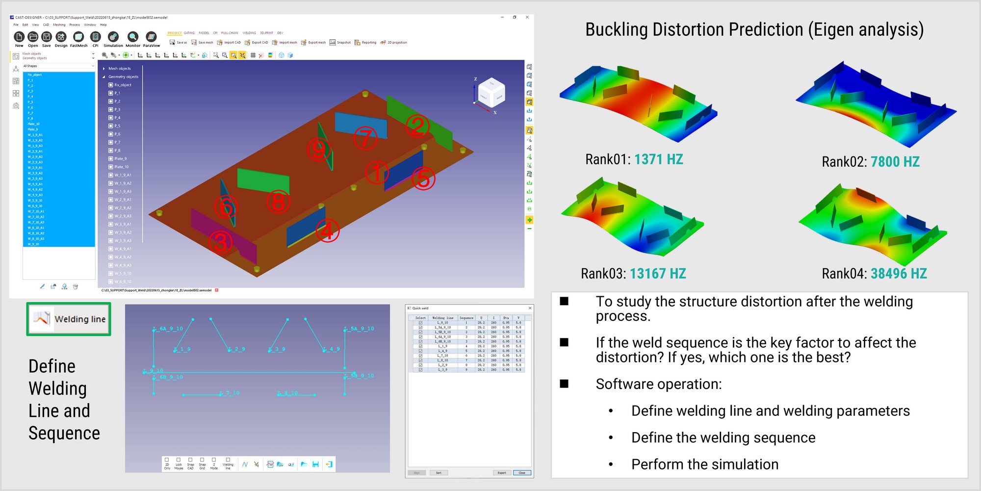
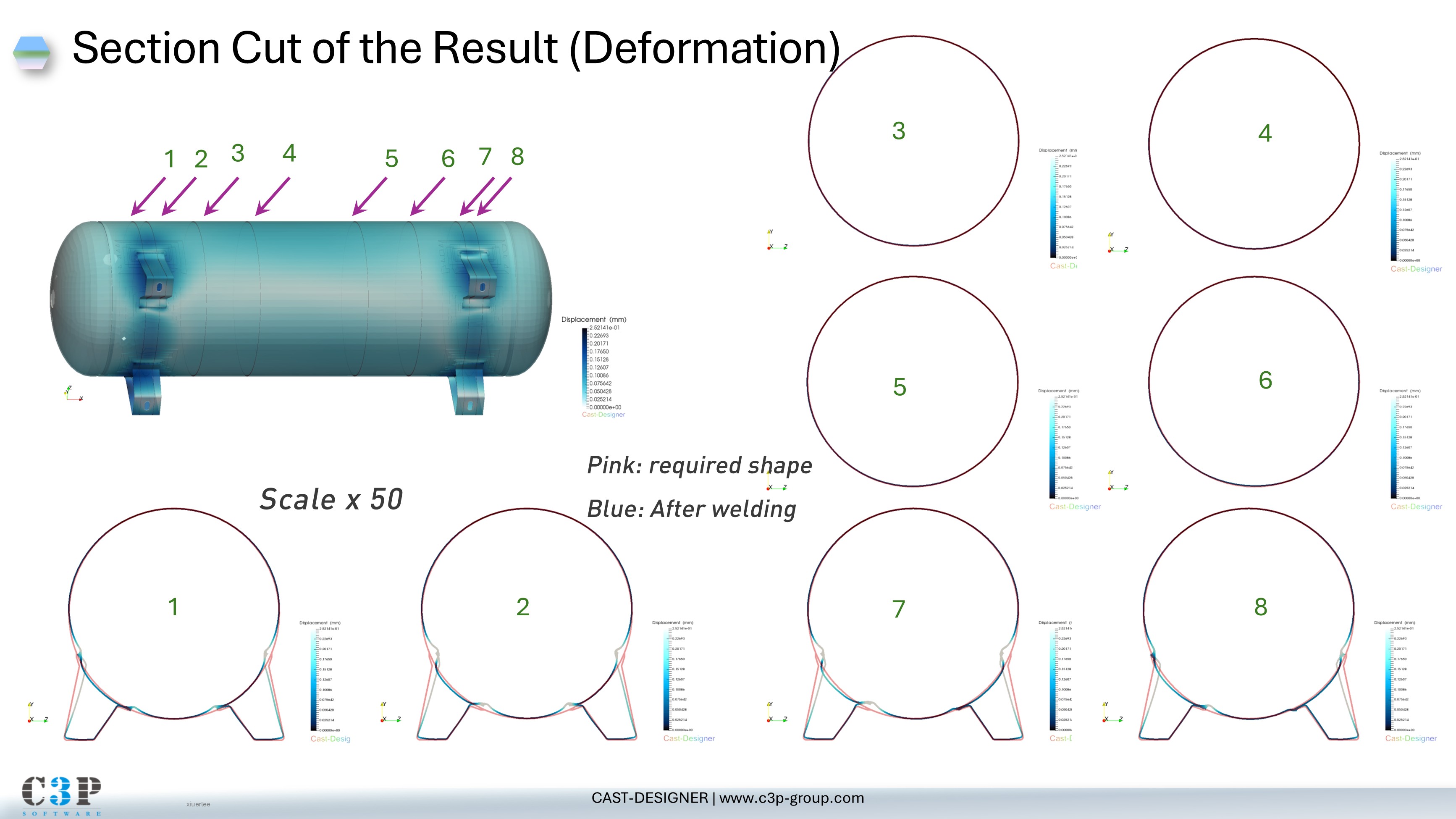
Weld distortion is a frequent problem in welding. Techniques like tack welding, fixturing, and advanced methods (pre-offset, trail cooling) can be optimized via simulation to predict and achieve zero distortion.
Residual stress impacts weldment service life. Cast-Designer WELD generates a 3D stress map for fatigue/creep analysis, optimizing design to avoid part rejection and enhance longevity.
Master the Heat Affected Zone (HAZ) to minimize stresses and deformations. Simulation ensures this sensitive zone remains narrow and controlled.
Simulates material addition, making weld bead shape a true result of the process—not an assumption.
Optimize part geometry and process parameters early in design to avoid costly engineering changes.
User-defined sequencing and control of parameters (energy input, speed, material) for optimal weld quality.
The weldability (also known as joinability) of a material refers to its ability to be welded. Many metals and thermoplastics can be welded, but some are more easily welded than others. A material's weldability is used to determine the welding process and to compare the final weld quality with other materials.
A built-in calculator helps users calculate many useful results for weldability analysis, supporting the planning and optimization of welding tasks including weldability, cooling time, preheating temperature, and required filler metal quantities.
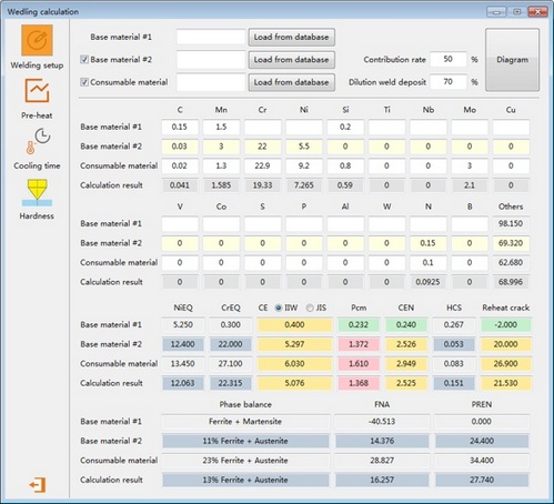
Weld calculator interface
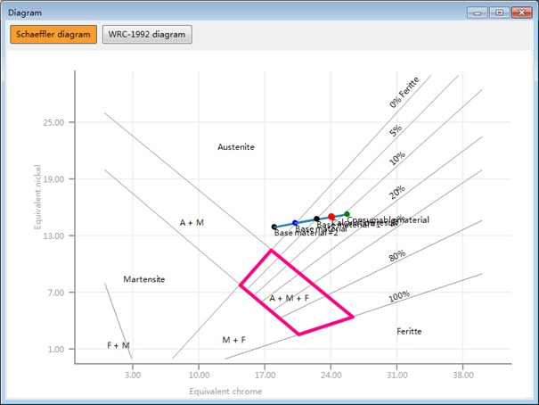
Schaeffler diagram
The SmartWeld optimization and analysis tools have been developed to perform weld analysis and provide optimal weld schedules for CO2 continuous wave laser welding, pulsed Nd:YAG laser welding, and non-consumable arc welding processes.
The optimization methodology consists of mixed genetic and gradient-based algorithms to query semi-empirical and nonlinear algebraic models. The optimization output provides heat-input-efficient welds for user-specified weld dimensions. User querying of all weld models is available to examine sub-optimal schedules.
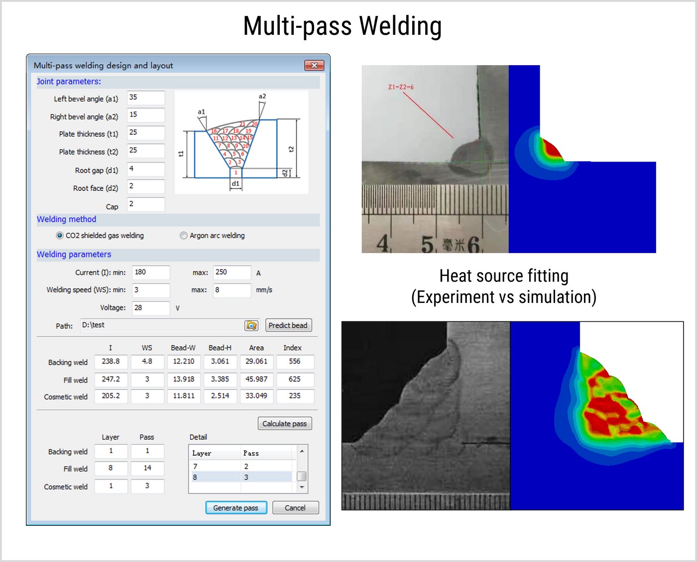
Comprehensive welding simulation solutions integrating advanced heat source modeling, multi-pass optimization, and weld pool dynamics
CAST-DESIGNER WELD incorporates an extensive heat source database for various welding processes, requiring only basic parameter inputs for accurate simulation. Our advanced thermal modeling captures the complex physics of different welding techniques.
Our proprietary line heat source technology accelerates simulation times by 10-30x while maintaining accuracy. Users define heat source length parameters to balance computational efficiency with result precision.
Advanced element activation/deactivation algorithms precisely simulate weld bead deposition, significantly enhancing simulation accuracy for additive welding processes.
Critical for steel construction and pressure vessels, multi-pass welding presents significant challenges with defects and residual stresses that impact structural integrity and fatigue life.
Traditional trial-and-error approaches are impractical when evaluating thousands of possible welding sequences. Our solution combines:
The system evaluates thermal cycles, phase transformations, and mechanical responses to identify optimal welding patterns from tens of thousands of possible configurations.
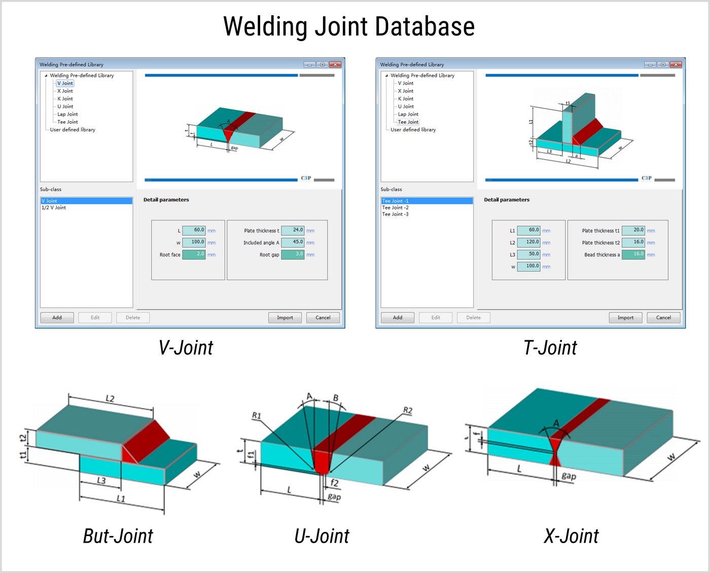
CAST-DESIGNER WELD includes a comprehensive joint database covering:
The database supports:
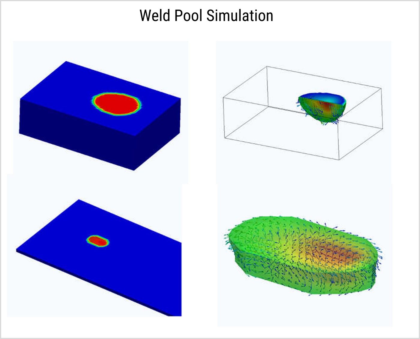
Our advanced CFD solver captures the complete weld pool physics including:
The simulation provides detailed visualization of:
Advanced simulation solutions for optimal spot welding performance and quality control
Resistance spot welding permanently joins metal parts by melting and fusing materials through localized heat generated by electrical resistance. The process creates a strong metallurgical bond as the molten materials cool rapidly under electrode pressure.
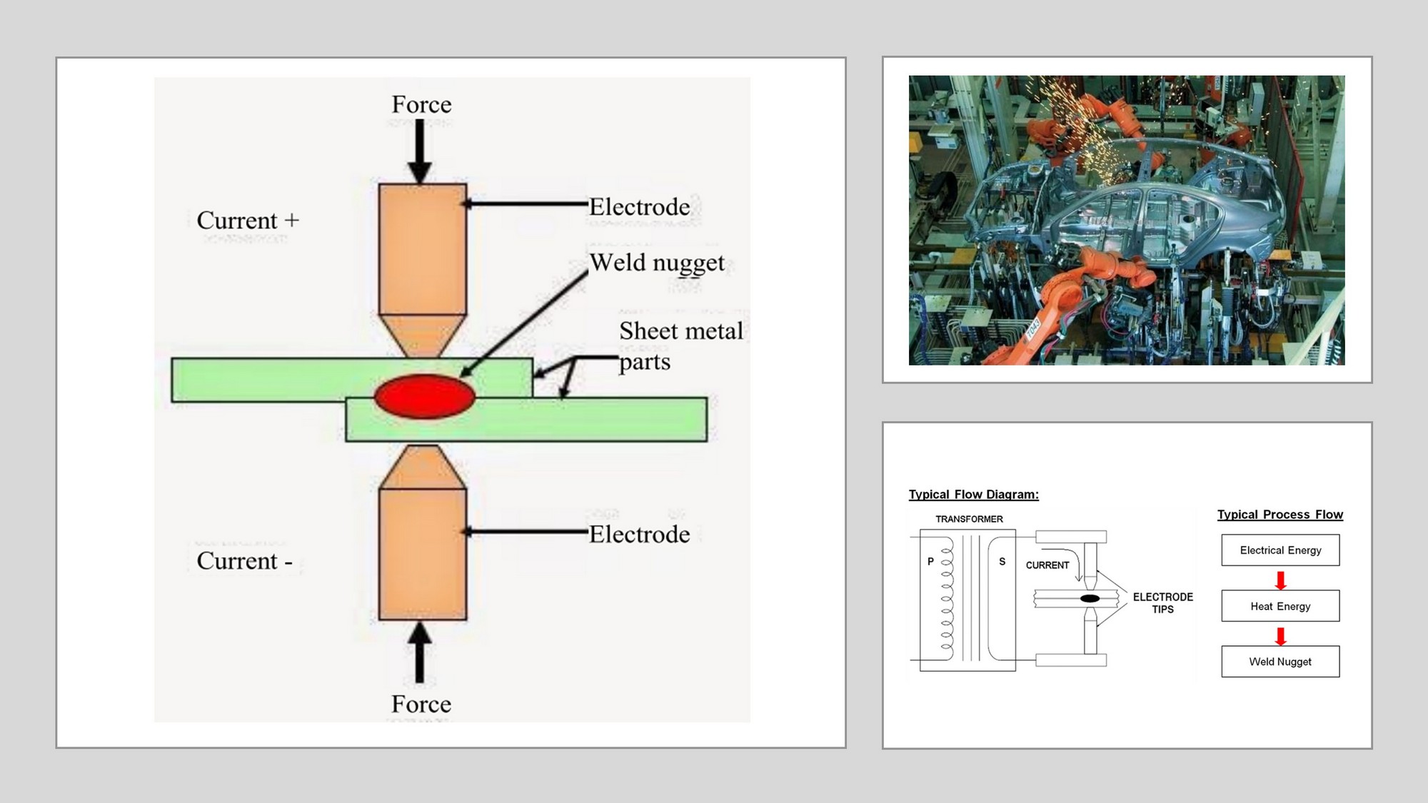
Heat generation follows Joule's Law (Q=I²Rt), where resistance to current flow between electrodes creates localized melting. CAST-DESIGNER WELD precisely simulates this thermo-electrical-mechanical process for optimal parameter selection.
The weldability lobe graphically represents acceptable welding parameter ranges that produce quality welds. Simulation identifies the optimal process window to:
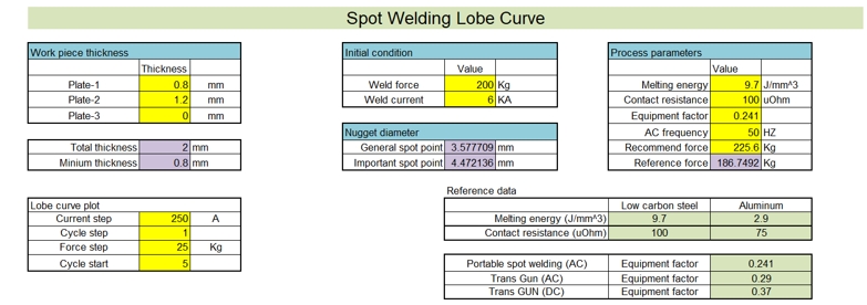
Weldability Lobe Curve
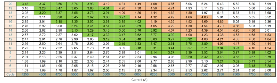
Current Parameter Table
Modern manufacturers rely on weldability lobe simulation to select parameters that meet strict joint stretch requirements while maximizing electrode life and energy efficiency.
CAST-DESIGNER WELD provides comprehensive 3D simulation of the spot welding process with advanced modeling capabilities:
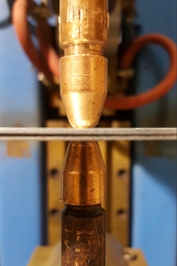
Actual Spot Weld
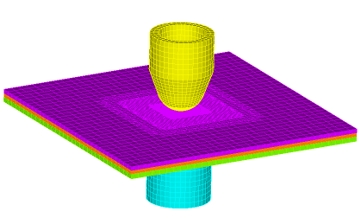
Simulation Model
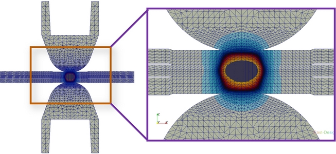
3-Layer Assembly (1.0+0.8+1.2mm)
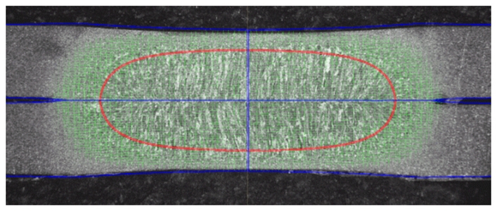
Simulated vs Actual Nugget
Advanced visualization of the spot welding thermal cycle and nugget formation:
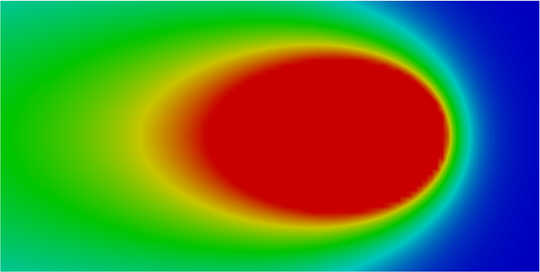
Temperature Distribution
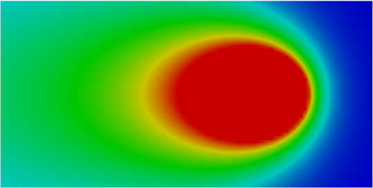
Nugget Formation & Cooling
The simulation captures key process phenomena including contact resistance changes, thermal expansion, and phase transformations during heating and cooling cycles.
Advanced thermo-mechanical simulation for welding distortion prediction in complex assemblies
The Smart Welding Assembly module in Cast-Designer WELD utilizes fast thermo-mechanical coupled simulation methods to predict assembly distortions in large, complex welded structures. The solution combines computational efficiency with industrial-grade accuracy for practical engineering applications.
Originally proposed by Ueda for residual stress measurement, this elastic FE simulation method has become the industry standard for predicting welding distortion in large structures.
Our enhanced methodology applies thermal loads directly based on welding process parameters for improved accuracy:
Advanced multi-criteria optimization using AI-driven methods to achieve optimal welding results
CAST-DESIGNER optimizer executes multi-criteria non-linear optimization using Design of Experiments (DOE), Genetic Algorithms (GA), and Particle Swarm Optimization (PSO) - advanced artificial intelligence techniques for industrial applications.
The system intelligently evaluates each iteration's results (distortion, stress, etc.) and automatically adjusts variables (velocity, sequence, etc.) until targets are achieved. Complex user formulas are supported without programming, and parallel optimization dramatically reduces lead times.
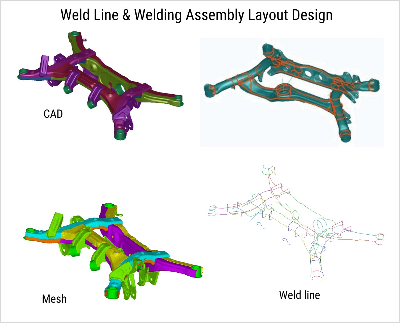
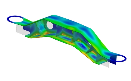
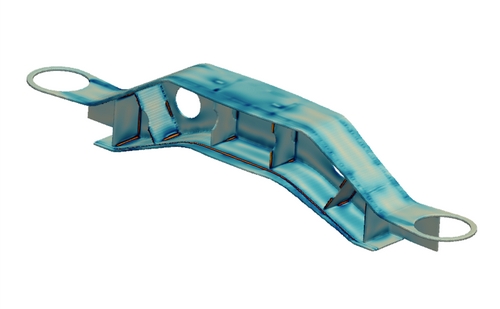
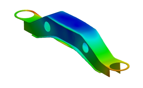
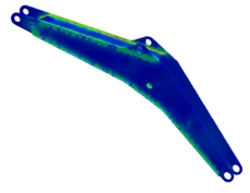
Vehicle Chassis Bracket Welding Sequence Optimization
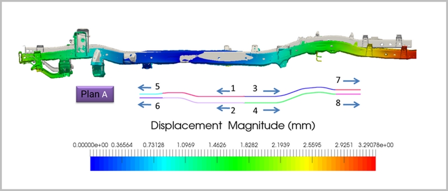
Initial Welding Sequence
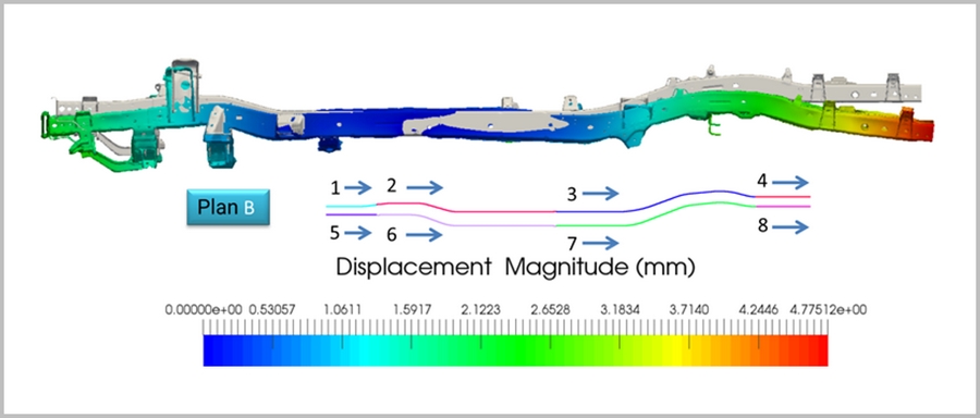
Optimized Welding Sequence
Advanced welding simulation software for thermal analysis, weld distortion prediction, residual stress analysis, and welding process optimization.
Cast-Designer Welding supports a wide range of materials:
📧 nageswarababu.k@nestechglobal.com | 📞 +91-8056372404
Request a demo for Cast-Designer Welding Software
Real-world applications demonstrating our welding simulation capabilities across industries
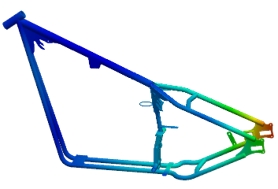
Welding of thick/thin-walled chassis and body-frame parts
For Automotive OEM and selected suppliers, railway and aerospace industry.
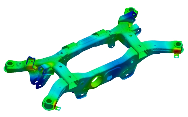
Temperature distribution
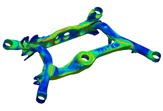
Residual stress after welding
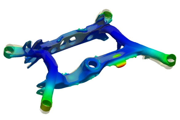
Distortion after welding
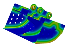
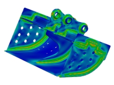
Thin wall frame assembly
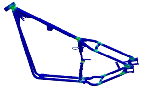
Residual stress after welding
Distortion after welding
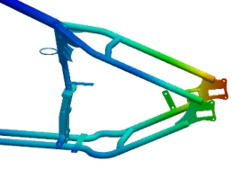
Distortion after welding (enlarged)
Large structure assembly with multi-pass welding
Temperature distribution
Residual stress after welding
Bogie frame distortion
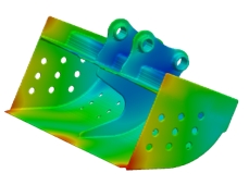
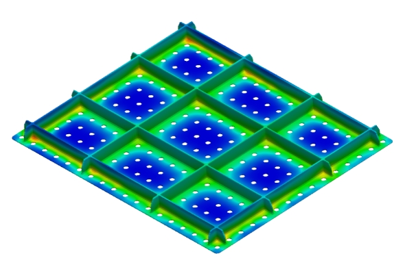
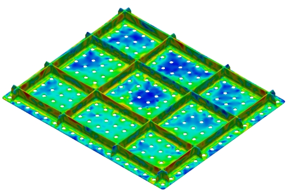
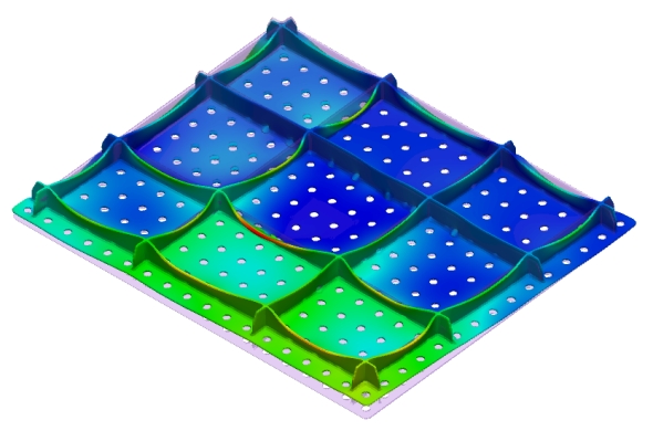
Shipbuilding and construction equipment
Temperature distribution
Temperature distribution
Residual stress after welding
Distortion after welding
Marine and construction equipment
Temperature distribution
Residual stress after welding
Distortion after welding
Residual stress control for dynamic components
ITER is the world’s largest fusion experiment. 35 nations are collaborating to build and operate the ITER Tokamak, the most complex machine ever designed, to prove that fusion is a viable source of large-scale, safe, and environmentally friendly energy for the planet.
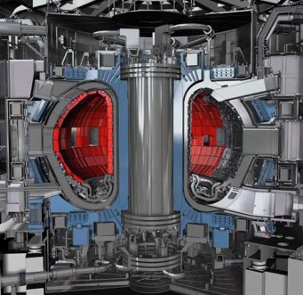
Actual assembly
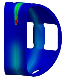
Temperature distribution
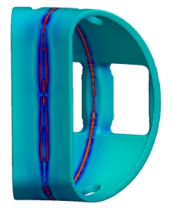
Residual stress after welding
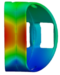
45m x 68m x 28m assembly
Nuclear, energy, and marine applications
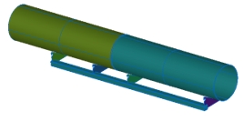
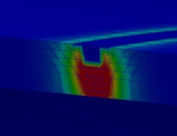
Pipe multi-pass welding
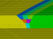
Weld layout design
First pass temperature
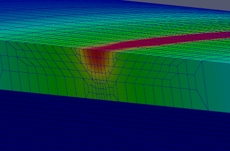
Final pass temperature
Residual stress after welding