▲
Left Logo Right Logo
Menu
  • Slide 1

  • Slide 2

  • Slide 3

  • Slide 3

  • Slide 3

C3P Cast-Designer for Gravity Casting

Cast-Designer for Gravity Casting - Design to Simulation

FLOW AND SOLIDIFICATION SIMULATION FOR GRAVITY CASTING

Cast-Designer provides unique Quick Design tool, Accurate CFD based simulation and AI Optimization Tools.

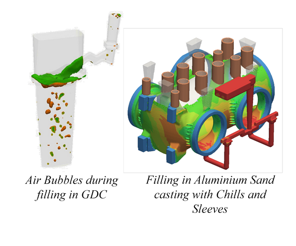
Gravity Casting Flow

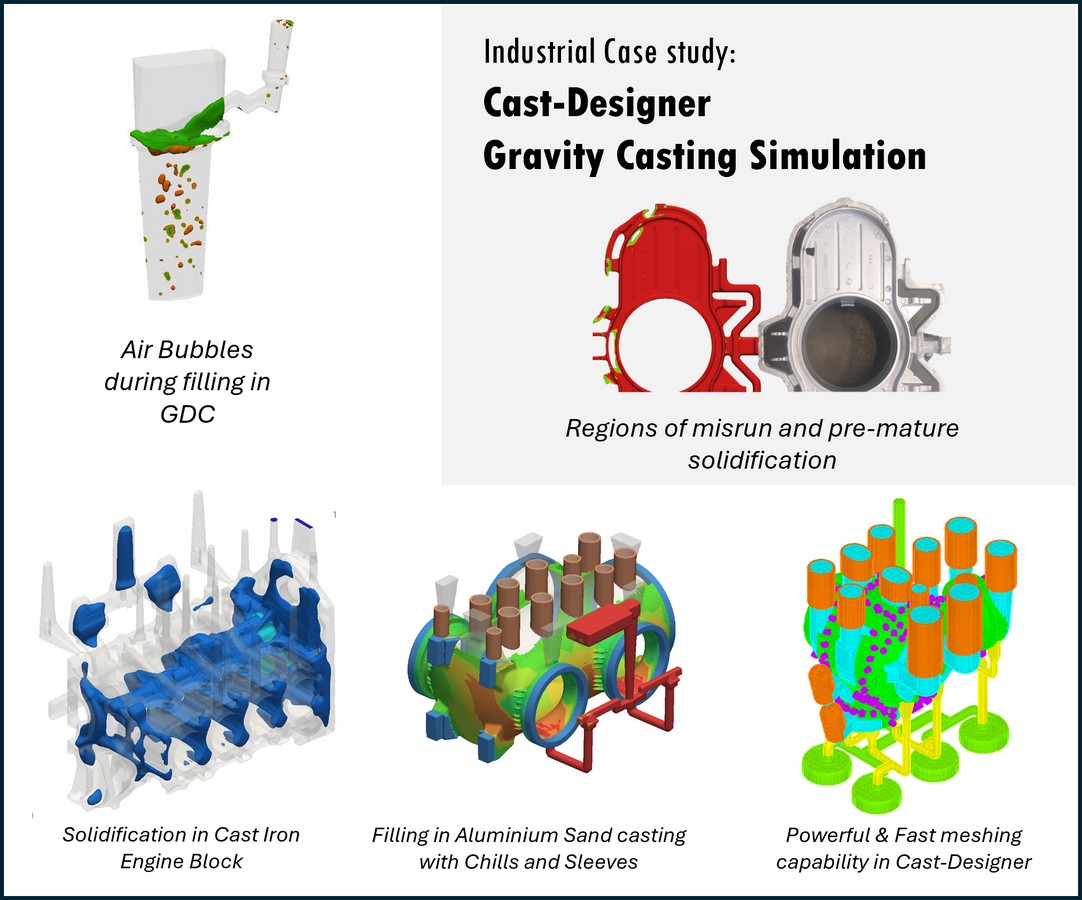
Turbulence, Oxides, Air Entrapment, Bubble Movement: Slow filling or heavy temperature loss may cause cold-shut or pre-mature solidification or un-filling. The turbulence combined with high temperature during filling may lead to inclusions. Air bubbles in the heavy turbulence area forms oxide layers, that may get trapped in areas where fluid flow is restricted and may create locally weaker region in the component. These defects can be precisely analysed which helps designers optimize their gating system and better position for the vents.

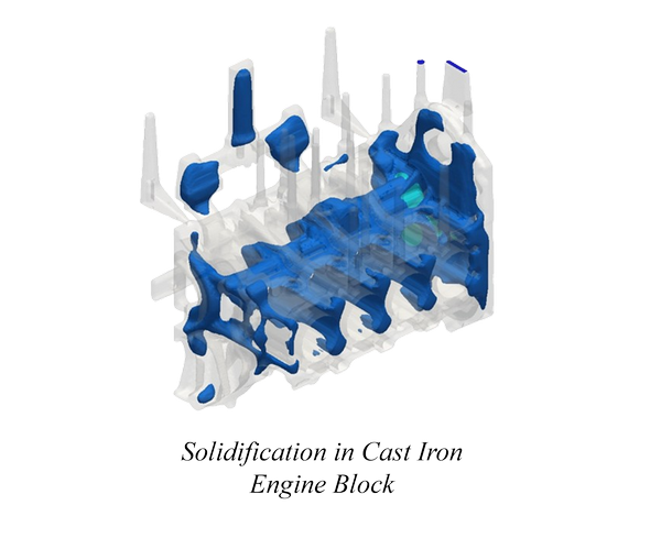
Gravity Casting Solidification

In the casting solidification process, it combines the heat transfer, metal flow and density & phase change. The cast iron solidification also considers eutectic solidification of cast irons along with the formation of inoculation, austenite, carbide and graphite precipitation.

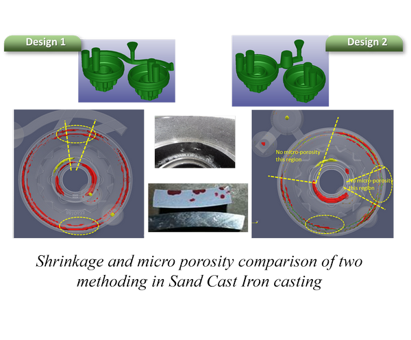
Shrinkage Porosity & Niyama Micro Porosity

Accurately predicts the shrinkage porosity, also considers the expansion of cast iron and the density variations that occurs during the cooling process in the solidification. Cast-Designer accurately predicts the Niyama / dimensionless Niyama micro-porosity occurring late in the solidification stage.

NEW MICROSTRUCTURE MODEL IN CAST-DESIGNER

Cast-Designer provides unique Quick Design tool, Accurate CFD based simulation and AI Optimization Tools.

New Microstructure Model in Cast-Designer

A new microstructure model developed by C3P software has been integrated into Cast-Designer.

This software facilitates coupled calculations for:

  • Thermal microstructure
  • Porosity
  • Inoculation

It utilizes advanced material science and technology to evaluate:

  • The phase factor
  • Transformations during manufacturing processes

Manufacturing processes include:

  • Casting, Welding, Heat Treatment, and Hot Forming

This solver is designed for use with materials like:

  • Steel, Aluminum and Stainless steel

Key features:

  • Dedicated material database required
  • No need for CCT or TTT curves
  • Can replicate formation of microstructures
  • Assesses mechanical properties based on computed microstructure

The microstructure solver examines:

  • Evolution of different phases
  • Predicts local density variations
  • Provides more precise forecasts of porosity

CASTING HEAT-TREATMENT SIMULATION

Cast-Designer provides unique Quick Design tool, Accurate CFD based simulation and AI Optimization Tools.

CASTING HEAT-TREATMENT SIMULATION

The heat treatment simulation technology, enhancing both component and process design.

This advanced software features:

  • Heat treatment simulation module
  • Integration of thermal and solid mechanics
  • Finite element analysis

With Cast-Designer, engineers can accurately forecast:

  • Residual stress states in components post-heat treatment
  • Evolution and final volume fractions of metallurgical phases
  • Hardness and potential part distortion

The software's analysis tool provides:

  • Seamless combination of multiphase material model
  • Advanced diffusive phase transformation kinetics
  • Martensitic phase transformation kinetics
  • Comprehensive simulation capabilities
  • Superior design outcomes

ADVANCED SIMULATION CAPABILITIES

PREDICTION OF GRAIN STRUCTURE and GAS POROSITY

PREDICTION OF GRAIN STRUCTURE

The CDCA (Cellular Automaton) model in CAST-DESIGNER provides microscopic simulation of solidification:

  • Cellular Automaton Principle:
    • Discrete lattice of cells representing liquid/solid phases
    • Each cell evolves based on neighbor states and physical rules
    • Time-step simulation of nucleation and growth
  • Grain Formation Process:
    • Initial random nucleation sites based on alloy properties
    • Dendritic growth influenced by local temperature gradient
    • Crystallographic orientation assignment
  • Output Capabilities:
    • 3D visualization of grain morphology
    • Grain size distribution statistics
    • Prediction of columnar/equiaxed transition

GAS POROSITY SIMULATION

Models formation of gas pores during solidification:

  • Formation Mechanisms:
    • Gas rejection from liquid during phase change
    • Entrapped air from mold filling
    • Mold-gas reactions
  • Simulation Approach:
    • Couples hydrogen diffusion with solidification front
    • Tracks bubble nucleation and growth kinetics
    • Accounts for local pressure conditions
  • Industrial Applications:
    • Predicts surface blowhole defects
    • Evaluates degassing treatment effectiveness
    • Optimizes venting system design

HYDROGEN POROSITY SIMULATION

Specialized prediction of hydrogen-induced defects:

  • Key Physics:
    • Hydrogen solubility difference between liquid/solid phases
    • Diffusion-limited bubble growth
    • Interaction with dendritic structure
  • Unique Model Features:
    • Multi-phase hydrogen redistribution
    • Bubble-dendrite mechanical interaction
    • Pressure-dependent nucleation threshold
  • Process Optimization:
    • Predicts critical hydrogen content thresholds
    • Evaluates effectiveness of degassing methods
    • Quantifies porosity risk for different cooling rates

INTEGRATED SIMULATION BENEFITS

  • Simultaneous prediction of microstructure and porosity
  • Quantitative comparison of different process parameters
  • Reduces trial-and-error in foundry operations
  • Enables defect-free casting design

Cast-Designer for Gravity Casting - Design Features

Gating Design Wizards
Smart Riser, Feeder & Chil Design
Pourig System Design
Template Gating Library
Library of Standard Parts
QuickCast Flow Simulation
QuickCAST vs CFD Flow
New Casting Material Generator
Media Flow in Cooling Channels
Part Ejection Simulation

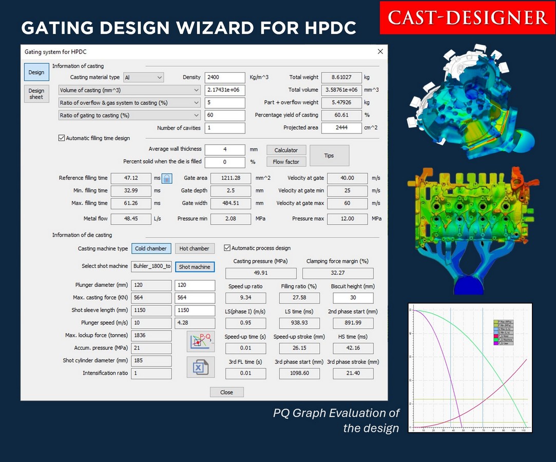
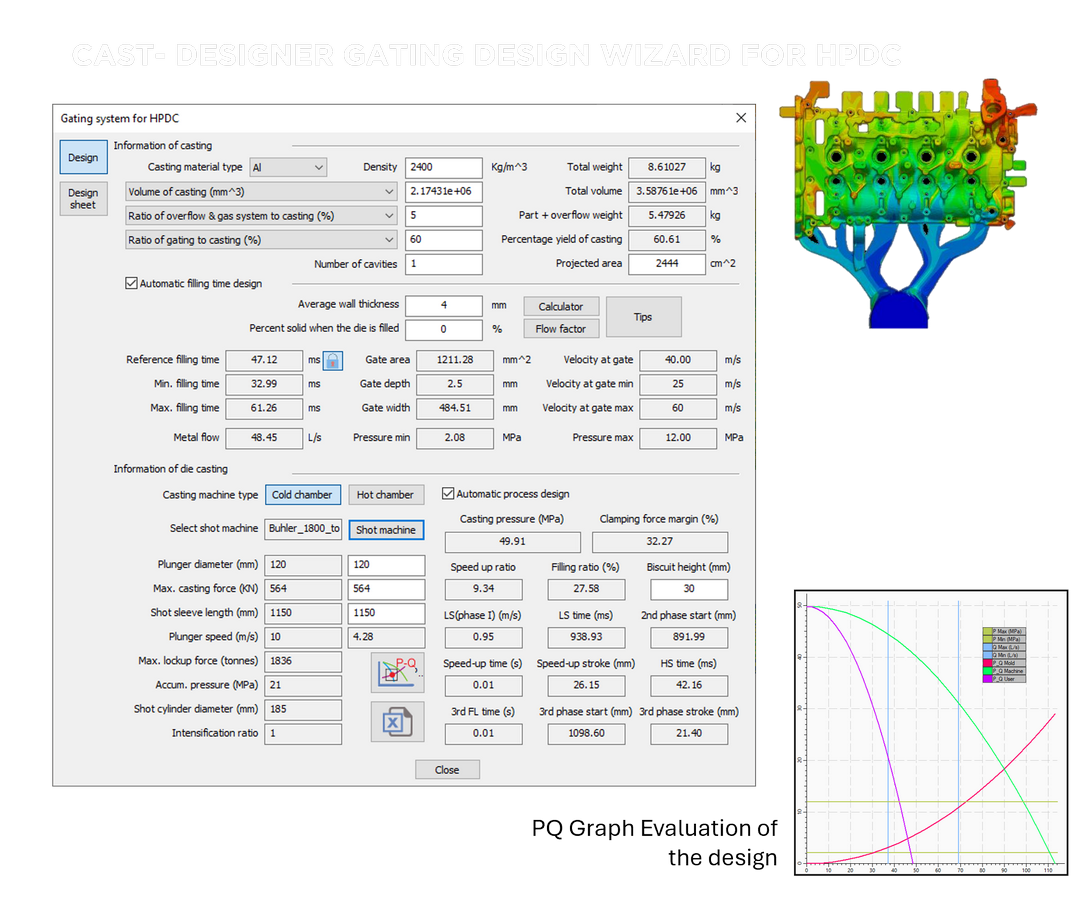
HPDC Gating Design Wizard

The HPDC Gating Design Wizard streamlines gating design by accepting key casting inputs and delivering optimized results quickly and accurately.

  • Inputs: casting weight, projected area, material, shot machine, and biscuit size.
  • Generates PQ² graph to validate shot machine capacity.
  • Outputs include filling time, ingate velocity, required ingate area, phase velocities, and shift times.
  • Calculates casting pressure, clamping force margin, and runner cross-sections for Smart Runner Design.
  • Ensures fast, efficient, and reliable gating setup with minimal manual effort.

QuickCast Flow Simulation

QuickCast enables rapid flow simulation in minutes by simply placing ingates with a point, direction, and weight factor. Ideal for early-stage design, it helps optimize part orientation and gating layout quickly.

  • Fast simulation with minimal input
  • Visualizes flow from each ingate, flow length, filling time, gas entrapment, and last fill region
  • Supports up to 1-million mesh models in under 5 minutes
  • Reduces design iterations, time, and cost

QuickCast Flow vs CFD Flow Comparison

QuickCast enables rapid flow simulation in minutes by simply placing ingates with a point, direction, and weight factor. Ideal for early-stage design, it helps optimize part orientation and gating layout quickly.

  • Fast simulation with minimal input
  • Reduces design iterations, time, and cost

Create Runner CAD Geometry in Cast-Designer

Casting Simulation Services
Runner Centre Lines

Place Sprue. To create runner, select an ingate (created in previous step) and pick a point towards sprue, runner automatically created as per width of the ingate size.

Casting Simulation Services
Auto Runner Sections

select other ingates and points of the desired location of the runner on screen, runner automatically created with correct width, draft, height as required for the ingate

Casting Simulation Services
Auto Runner in 3D

View runners in 3D, runner section width and height gradually reduced with proper draft angle. Each runner width is as per the width required for the ingate.

Casting Simulation Services
Auto Merge Runners

Select 1st runner as master and select 2nd to merge, runner section of the 1st runner automatically adjusted where 2nd runner is merging. Similarly in the other side runners.

  • Create fully parametric 3D runners in Minutes. From defined ingate and biscuit positions, our system auto generate a complete 3D runner system that seamlessly connects ingates and biscuits.

COMPLEX 3D RUNNER GENERATION USING 3D PROJECTION

Cast-Designer simplifies complex 3D runner creation using its built-in ParaCAD system. Just define the workspace, build the 3D die face and addendum, and use the 3D runner projection tool to generate a CAD-based 3D runner system with ease.

  • Features like ingate, overflow also follows the 3D profile

FastCooling Simulation Example

RED colored region indicates thick region and as well as that cooling is not sufficient, may leave a shrinkage porosity

FastCooling Simulation

Optimize Cooling System Design

Cast-Designer revolutionizes cooling system design with SmartCooling and FastCooling, enabling rapid analysis during the early design stage—without requiring full mold geometry or detailed HTC data.

  • Get cooling analysis results in just 3–5 minutes using casting and cooling channel geometry.
  • Modify cooling layout or parameters and instantly evaluate the effect on casting thermal performance.

This fast, geometry-based approach helps reduce development time, improve product quality, and extend die service life.

Artificial Intelligence Tools: SmartCooling

SmartCooling automates die casting cooling system design using AI to create optimized, efficient cooling layouts. The process is 10–30x faster than traditional methods and follows a powerful 3-step approach:

Step 1: Define Cooling Regions & Materials

Assign key regions based on metal flow—up to 6 main zones and 24 sub-regions. Set casting/mold materials, cooling properties, and production targets. This forms the foundation for intelligent cooling layout planning.

Step 2: Auto Generate Cooling Channels

The AI engine uses defined parameters to auto-generate a complete cooling system with parametric 3D geometry—supporting both standard and jet cooling types. This is the core of SmartCooling intelligence.

Step 3: Optimize Cooling Channels Design

Run FastCooling Analysis to evaluate performance. Instantly see the effect of any changes in channel design, position, or cooling power—enabling fast, data-driven optimization and design decisions. An Larger Example shown above.

Media Flow in Cooling Channels

In complex cooling systems, media flow within the channels can be quite intricate. Performing a thermal and flow simulation provides a detailed examination of both the media flow and temperature distribution. Furthermore, the dynamic heat transfer coefficient (HTC) can be derived from the results of the simulation, which can be used in the most accurate Full-Mould Cyclic Flow-Solidification Simulation.

Step 1: Define Media Inlets & Outlets

Assign all key parameters for the flowing medium hot or cold

Step 2: Get Media flow inside cooling channels with dynamic HTC value

Complex cooling system in GIGA casting, now can be effectively optimized.

Die-Spray Optimization: Boost Die Life & Efficiency

Die-spray is crucial in die casting—poor spray causes thermal shock, die damage, and downtime.

  • Protects critical die areas and reduces maintenance
  • Extends die life and improves casting quality
  • Simulates nozzle positions, spray timing, die temperature, and surface shape
  • Ensures optimal spray coverage and cooling balance
  • Enhanced Accuracy: Generates dynamic HTC for precise full-cycle simulation and better process control

Part Ejection Simulation

Die casting part quality can be affected during ejection, where parts separate from mold surfaces under force.

The ejection force depends on metal shrinkage and friction at the contact surfaces. Since ejection happens quickly, the static friction coefficient is key to accurate simulation.

Simulation Highlights:

  • Full mold stress simulation: Solidification + Stress with contact pressure
  • Supports solid or shell models
  • Couples with Cast-Works/CDPE for ejection process analysis
  • Outputs: Ejection time, casting temperature, residual stress, contact pressure
Full Mould Analysis

HPDC Gating Design Wizard

The HPDC Gating Design Wizard streamlines gating design by accepting key casting inputs and delivering optimized results quickly and accurately.

  • Inputs: casting weight, projected area, material, shot machine, and biscuit size.
  • Generates PQ² graph to validate shot machine capacity.
  • Outputs include filling time, ingate velocity, required ingate area, phase velocities, and shift times.
  • Calculates casting pressure, clamping force margin, and runner cross-sections for Smart Runner Design.
  • Ensures fast, efficient, and reliable gating setup with minimal manual effort.
Cast-Designer Stress & Distortion analysis of casting simulation

Stress & Distortion

With the Cast-Designer mechanical stress module, the user can make the stress and distortion analysis. The following result could be obtained after the simulation:

  • Casting and mould stress distribution
  • Part deformation and distortion
  • Compensation for part deformation and distortion
  • Displacements
  • Gap formation between the casting and mould
  • Predict elastic springback
  • Hot tearing
  • Die life fatigue
Cast-Designer Fast Cooling Channel analysis for casting simulation

Cooling System Design

Cooling channel Calculator & Advisor Wizard

Cast-Designer introduced a cooling channel calculator, it can help the user calculate the total length of the cooling channel with a given production rate. The utility considers many factors such as the part mass and casting alloy, mould size, production rate, cooling channel diameter, media flow speed and heat affection rate. The final result will be a cooling channel diameter and total length.

Now Cast Designer includes One-Button Cooling System Design from Version 6.2

Fast Cooling Anlysis

Cast-Designer introduces fast cooling system analysis method to help designer check the cooling system design at the very early stage, it is fully integrated to the cooling system design interface and the user can get result within 3 to 5 minutes.

Cast-Designer Production Optimization for HPDC and GDC casting simulation

Production Optimization with Cast-Designer

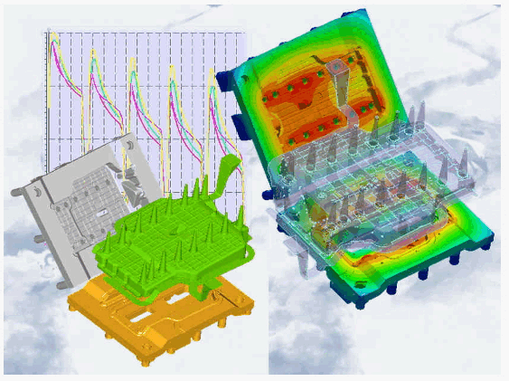
Cast-Designer’s Production Optimizer intelligently adjusts die spray, cooling/heating channels, and cycle timings to maintain optimal mould temperature and boost productivity. It helps avoid defects like cold shuts or die soldering while improving die life and reducing maintenance costs.

  • Considers complete cooling/heating systems with individual channel control.
  • Supports different die sprays and coatings for thermal efficiency.
  • Automatically optimizes cycle timing for best quality and cost.
  • Improves die life and reduces operational downtime.
  • Provides quick production cost estimates for quotations and cost control.
Cast-Designer Production Optimization for HPDC and GDC casting simulation

Full Chain Simulation

Cast-Designer enables full chain simulation by exporting casting results to external CAE tools for structural analysis and lifetime prediction. This provides a more realistic representation of part performance under "as-cast" conditions, including key casting defects.

  • Simulates casting with actual defects like shrinkage porosity, micro porosity, and residual stresses.
  • Enhances structural analysis accuracy by evaluating manufactured part strength—not just design intent.
  • Direct export to MSC Nastran and NEI Nastran with mapped material properties.
  • Supports ASCII CDF format for custom CAE integrations, as documented in the user manual.

Cast-Designer Supported Casting Processes

Cast-Designer HPDC Simulation

HPDC & GIGA Casting Simulation

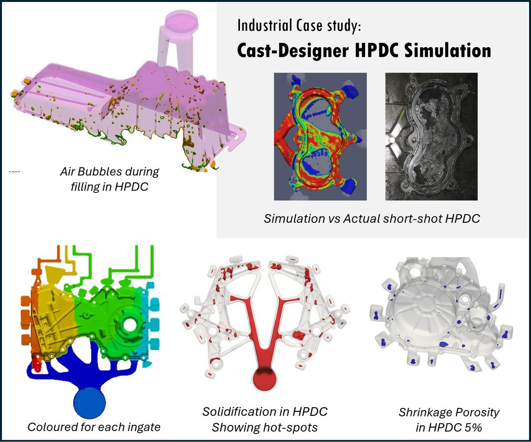
Cast-Designer uses advanced CFD technology to simulate HPDC processes with precision. It helps optimize gating, venting, and process parameters to improve quality and reduce defects. Extensive support for GIGA Castings

  • Gating Design Advisor follows NADCA standards for full guidance on gating systems.
  • Considers surface tension, slushy flow, turbulence, splash, and wall pull-away effects. Provides velocity, pressure, material age, and gate-wise flow paths.
  • Simulates shrinkage porosity with intensification pressure.
  • HPDC / GIGA Casting module comes with many industry's unique quick design tools.
  • More Details
Cast-Designer Stress & Distortion analysis of casting simulation

Gravity Casting Simulation

With the Cast-Designer mechanical stress module, the user can make the stress and distortion analysis. The following result could be obtained after the simulation:

  • Casting and mould stress distribution
  • Part deformation and distortion
  • Compensation for part deformation and distortion
  • Displacements
  • Gap formation between the casting and mould
  • Predict elastic springback
  • Hot tearing
  • Die life fatigue
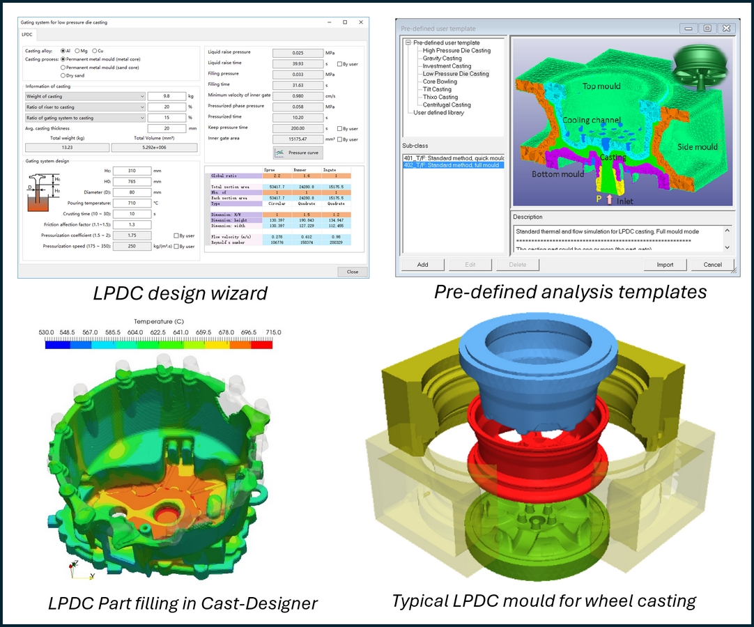
Cast-Designer for Low Pressure Die Casting for casting simulation

Low-Pressure Die Casting Simulation

Cast-Designer’s can simulate real-world casting conditions in LPDC. It features a powerful design wizard, supports variable pressure inputs, and offers pre-defined templates for quick and efficient process setup. Cast-Designer ensures precise thermal control through detailed modelling of cooling systems and timing.

  • Includes a design wizard for phase-wise LPDC setup and parameter definition to simulate realistic inlet conditions..
  • Models cooling channels and spray systems for effective heat management.
  • Simulates cooling mechanism timing to maintain thermal balance of the mould.
  • Helps optimize die design and casting quality by reducing thermal defects.
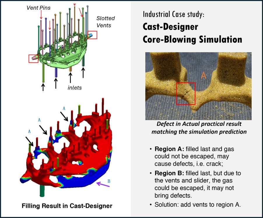
Cast-Designer Core Shooting Core blowing simulation

Core Blowing Simulation

Cast-Designer’s core blowing simulation helps optimize the core filling process by analyzing how sand is blown into the core box. It allows users to adjust nozzle and vent positions to ensure proper filling, pressure, and sand density.

  • Determines the best nozzle configuration by adjusting number and positions.
  • Optimizes venting nozzle placement for efficient air escape.
  • Analyzes sand packing pressure inside the core box.
  • Evaluates final sand density distribution for uniform compaction.
  • Helps prevent core defects caused by poor sand flow or air traps.
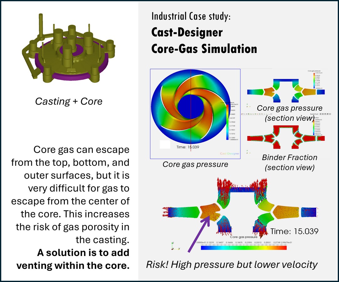
Cast-Designer Core gas in casting simulation

Core Gas Simulation in Casting

When molten metal heats sand cores, chemical binders decompose and release gas. Without proper venting, this gas can enter the metal, causing porosity defects. Cast-Designer simulates core gas behavior to help prevent such issues.

  • Predicts gas generation based on binder and temperature.
  • Simulates pressure buildup and gas flow inside cores.
  • Highlights high-risk zones for gas-related defects.
  • Optimizes vent design and placement.
  • Supports better core layouts for improved casting quality.

Cast-Designer Material Database

Cast Designer has more than 400 industry standard materialsin the database.

Casting Material

  • Cast iron: grey, SGI, CGI
  • White cast iron
  • Ni-Resist D2, D5
  • SiMo
  • Carbon steels
  • Stainless steels
  • Copper alloys
  • AlSi7 up to AlSi12
  • Mg-alloys
  • Zn-alloys

Mould materials:

  • Green sand
  • Dry sand
  • Chemical sand
  • Cr sand
  • Zr sand
  • Special sand
  • Silicon carbide
  • Graphite
  • Die
  • Insulation
  • Exothermic Sleeves
  • Filter

Frequently Asked Questions

What is Cast-Designer software used for?

Cast-Designer is a comprehensive casting simulation and optimization software used by foundry engineers and designers. It helps in gating system design, defect prediction, solidification analysis, and process optimization for various casting processes.

Which casting processes does it support?

Cast-Designer supports a wide range of casting processes including High Pressure Die Casting (HPDC), Gravity Casting, Sand Casting, Investment Casting, Low Pressure Die Casting, and Squeeze Casting.

What are the system requirements?

The software runs on Windows 10/11 64-bit systems. Minimum requirements include 16GB RAM (32GB recommended), a dedicated GPU with 4GB VRAM, and an Intel i7 processor or equivalent. SSD storage is recommended for better performance.

Is there a trial version available?

Yes, we offer a 30-day fully functional trial version. You can request it through our website, and our technical team will assist you with the installation and provide basic training if needed.

What kind of support do you offer?

We provide comprehensive support including email support, remote assistance, on-site training (optional), and regular software updates. Our support team is available during business hours with emergency support for critical issues.

Some of the Casting Simulation Results

  • Flow Velocity

    Flow Velocity

    In casting simulations, flow velocity is crucial for predicting how molten metal fills the mold. It helps identify issues like air entrapment, turbulence, and cold shuts, ensuring smooth flow, better mold filling, and improved casting quality.

  • Sample Image 2

    Flow Temperature

    In casting simulations, flow temperature is vital to ensure proper mold filling and solidification. It helps detect risks like cold shuts, misruns, and uneven cooling, enabling optimized gating design and improved casting integrity, surface finish, and mechanical properties.

  • Sample Image 3

    Air Enrapment

    In casting simulations, air entrapment indicates where air may get trapped during metal flow. Monitoring it helps prevent porosity, blowholes, and incomplete filling. Identifying air pockets early allows for better venting and gating design, improving overall casting quality and reliability.

  • Sample Image 4

    Flow Velocity Vector

    In casting simulations, flow velocity vector direction shows the path and behavior of molten metal within the mold. It helps identify turbulence, short-circuiting, and uneven filling, guiding gating system optimization to ensure smooth, uniform flow and high-quality castings.

  • Sample Image 5

    Fill Time Plot

    In casting simulations, the fill time plot shows how long molten metal takes to fill the mold cavity. It helps identify slow-fill zones, cold shuts, and misruns, enabling optimization of gating design for balanced filling, better quality, and defect prevention.

  • Sample Image 1

    Flow Oxides

    In casting simulations, the flow oxides plot highlights areas where oxides may form due to turbulent metal flow. This helps detect risks of inclusions, weak spots, and surface defects, allowing engineers to refine gating and pouring to minimize oxidation-related issues.

  • Sample Image 2

    Maximum Air Pressure

    In casting simulations, the maximum air pressure regions plot identifies areas where trapped air builds up during mold filling. High air pressure can lead to blowholes, porosity, or incomplete filling. This plot guides venting and gating improvements to enhance casting quality.

  • Sample Image 3

    Materail Trace Lines

    In casting simulations, the material trace lines plot tracks the path of molten metal during filling. It helps visualize flow patterns, detect dead zones, and analyze mixing behavior, enabling better gating design and ensuring complete, uniform filling for high-quality castings.

  • Sample Image 4

    Solidification

    In casting simulations, solidification analysis reveals how and where molten metal solidifies in the mold. It helps identify shrinkage defects, hot spots, and non-uniform cooling, allowing optimization of riser design and cooling rates to improve casting quality and integrity.

  • Sample Image 5

    Shrinkage Porosity

    Shrinkage porosity indicates areas where metal volume loss during solidification can create voids. Identifying these zones helps optimize riser placement, cooling rates, and solidification patterns, ensuring sound castings with improved structural integrity and reduced internal defects.

  • Sample Image 1

    Niyama Mirco-Porosity

    Niyama micro porosity predicts the likelihood of micro-porosity formation based on cooling rates and solidification conditions. It helps identify potential defects in fine details, enabling adjustments in gating, cooling systems, and mold design for improved casting quality..

  • Sample Image 2

    SDAS

    Secondary Dendrite Arm Spacing result reveals the cooling rate and solidification structure of the metal. It helps predict material strength, ductility, and defect formation, guiding process adjustments to optimize casting quality and mechanical properties.

  • Sample Image 3

    Tensile Strength

    Tensile strength results predict the material's resistance to deformation under stress. Analyzing these results helps identify potential weak points, optimize alloy composition, and adjust process parameters to ensure castings meet required mechanical properties and performance standards.

  • Sample Image 4

    Mould-Casting Gap

    Mold-casting gap formation during solidification indicates areas where metal shrinks as it cools, potentially leading to misruns or voids. Analyzing this gap helps optimize mold design and riser placement, ensuring complete fill and defect-free castings.

  • Sample Image 5

    Casting Crack Indicator

    The casting crack indicator highlights areas at risk of cracking due to thermal stresses or poor solidification. Identifying these regions helps optimize cooling rates, riser placement, and gating design, preventing cracks and improving casting integrity.

  • Sample Image 1

    Casting Warpage

    Casting distortion/warpage predicts deformation due to uneven cooling or residual stresses. Identify areas prone to shape changes, enabling process adjustments like cooling rate optimization and mold design modifications to prevent dimensional issues and ensure accuracy.

Our Casting Simulation Services

Casting Simulation & Methoding Services

For Gravity, Sand, HPDC, LPDC, Investment Castings

Check your casting and predict shrinkage, porosity, flow, air entrapment defects – without incurring tooling costs or waiting for trials. Assess your method for potential defects. Optimize it for quality and yield improvement ...learn more

Quality Improvement & Yield Optimization.

Casting Simulation Services

NESTech Services and Products

  • Engineering Services

    More Info

  • IT Software Services

    More Info

  • Cast Designer Software

    More Info

Why Choose NESTech as your CAD CAE Partner?

+ Drawings Created
+ Simulations done
+ Team Members
+ Years of Experience
Experience Icon

RICH EXPERIENCE

 We bring 25+ years of rich experience to every project, ensuring exceptional results and unparalleled reliability.
Experience Icon

ON-TIME DELIVERY

 With meticulous planning, streamlined processes, and a dedicated team, we ensure that every project is completed promptly and efficiently

Experience Icon

EXCELLENT COLLABORATION

 We foster a culture of teamwork, communication, and mutual respect, ensuring that every project benefits from the diverse perspectives and expertise of our team members.

Experience Icon

COST EFFECTIVENESS

  With a multitude of projects Completed and catering to various industries, we have demonstrated excellent business results at lower cost with our domain expertise.

Some of the Cast-Designer Software Customers

NESTech Logo info@nestechglobal.com

Addresses

Registered Head Office-India:
FFA-Ramani Mathura, 87 Ansari Street, Ram Nagar, Coimbatore 641009
Works-India:
23, Thaneer Pandhal Road, 6th Cross, Peelamedu, Coimbatore 641004
International: Germany & USA

Engineering Services

  • CAD Services
  • Product Design
  • PLM Services
  • CAE Simulation
  • Structural Engineering
  • Casting Flow Simulation
  • Cast Designer Software

IT Services

  • Software Development
  • ERP Services
  • Mobile App Development
  • AI and IOT
  • App Integration
  • Business Intelligence
  • Quality Assurance
Home Contact Us Careers
© NESTech Consulting Private Limited. All Rights Reserved.