Right Logo
Menu
⚙️ Complete Casting Engineering Platform
C3P Geo-Designer Software for
Design For Manfacturing

Geo‑Designer Advanced DFM Software

For Casting Industries · Design for Manufacturing

Upfront Manufacturability Evaluation

Geo‑Designer is an advanced upfront Design for Manufacturing (DFM) software developed for casting product designers, foundry engineers, and tooling engineers to evaluate casting manufacturability at the earliest stage of product development.

The software uses innovative Mass Distribution Index (MDI) technology to analyze 3D CAD geometry and quickly identify thermal hotspots, high mass regions, wall thickness variations, and manufacturing challenges — within minutes.

  • Immediate feedback during design stage
  • Optimize part geometry & feeding design
  • Reduce defects & minimize development time
  • 3D Iso‑surface visualization (like X‑ray / CT)
  • First‑Time‑Right casting designs
Geo Designer Capabilities
Detect manufacturing risks early — achieve First‑Time‑Right casting designs, reduce tooling modifications, trials, and overall costs.
“Geo‑Designer provides a simple but very effective tool to support casting process product and manufacturing design, it cuts at least 60% of design lead time, thanks to the state‑of‑art technologies.”
Prof. Z. Zhang, MSE Tsinghua University
-60%

Hotspot Detection, Gating, Riser & Feeding Gravity Casting

Design Optimization · Feeding Strategy · Yield Improvement

Understanding Hotspots in Gravity Casting

In gravity casting, molten metal enters the mold cavity under the influence of gravity and solidifies progressively from the mold walls towards the center. During solidification, metal undergoes volumetric contraction. If the last solidifying regions do not receive sufficient liquid metal from a feeding source, shrinkage porosity and internal voids can occur.

These last-to-solidify areas are known as thermal hotspots and are generally associated with:

  • Thick wall sections
  • Heavy masses and isolated volumes
  • Junctions of multiple walls
  • Boss and flange connections
  • Sudden changes in section thickness
  • Areas with poor directional solidification
How Geo‑Designer Identifies Hotspots

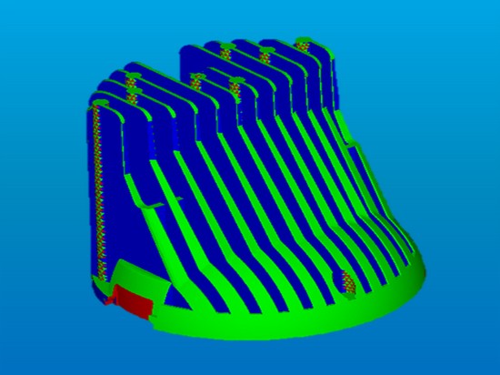
Geo‑Designer uses Mass Distribution Index (MDI) analysis to quickly evaluate the 3D CAD model and identify thermal hotspots within minutes. The software predicts regions with high thermal mass that are likely to solidify last and require feeding support.
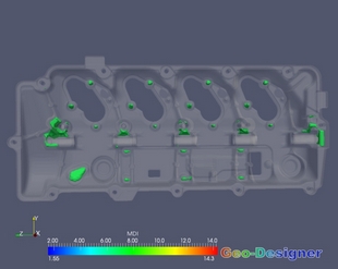
After adding riser & feeding system, MDI analysis verifies hotspot shift from casting into riser — confirming effective feeding.

Geo Designer Hotspot - Gravity Casting

1. Riser Location & Feeding Strategy

Geo‑Designer hotspot analysis helps determine:

  • Whether a riser is required
  • Optimum riser location
  • Number of risers required
  • Direction of feeding
  • Most critical regions requiring feeding
Result: Reduction of shrinkage porosity & improved internal soundness
feeding strategy

2. Riser Size & Yield Improvement

Add risers directly to geometry and verify:

  • Hotspot shifts from casting to riser
  • Riser becomes last region to solidify
  • Directional solidification toward feeder
  • Optimum riser dimensions
Yield: Smaller risers = higher casting yield, lower metal consumption
yield optimization

3. Thermo Sleeve Selection

Evaluate insulating and exothermic sleeves:

  • Whether a sleeve is required
  • Appropriate sleeve location
  • Required sleeve size
  • Improvement in riser efficiency
Benefit: Reduced riser volume, improved feeding distance
sleeve optimization

4. Chill Placement & Directional Solidification

Identify hotspot locations to decide:

  • Where chills should be placed
  • Size and number of chills required
  • How cooling path can be controlled
  • How to eliminate isolated hotspots
Result: Improved directional solidification & dimensional consistency
chill design

5. Rapid Gating & Feeding Iteration

Quickly evaluate multiple feeding concepts:

  • Add risers, sleeves, chills to CAD
  • Modify position and dimensions
  • Run MDI analysis repeatedly
  • Compare different feeding alternatives
Speed: Significant reduction in development time
rapid iteration

6. Support for Detailed Simulation

Provide a better initial design:

  • Major hotspots identified
  • Feeding concepts established
  • Riser positions optimized
  • Sleeve & chill strategies evaluated
Workflow: Geo‑Designer → Simulation → Production
simulation ready

Overall Benefits of Early Hotspot Detection & Feeding Optimization

  • Identify shrinkage-prone regions directly from 3D CAD
  • Develop effective riser and feeding strategies before tooling
  • Determine optimum number, location, and size of risers
  • Evaluate effectiveness of insulating and exothermic sleeves
  • Optimize chill placement to control solidification direction
  • Achieve proper directional solidification toward the feeder
  • Minimize shrinkage porosity and improve casting integrity
  • Optimize riser size and significantly improve casting yield
  • Reduce excess metal, melting energy, and machining costs
  • Quickly compare multiple gating and feeding concepts
  • Reduce dependence on foundry trials and guesswork
  • Start detailed simulation with optimized process design
  • Reduce development lead time
  • Achieve First-Time-Right gravity castings
hotspot detection riser optimization sleeve selection chill placement rapid iteration
Improve casting yield by up to 30%
Geo‑Designer acts as a rapid virtual engineering tool — enabling foundries to establish efficient gating and feeding strategies early, achieving higher quality, improved yield, lower costs, and fewer physical trials.

Geo‑Designer – Fast Virtual Trial for Gravity Casting Feeding Design First‑Time‑Right

Instead of relying solely on traditional trial-and-error methods, engineers can quickly analyze thermal hotspots, add risers, thermo sleeves, and chills, and repeatedly evaluate different feeding concepts in minutes.

This rapid optimization approach enables foundries to establish an efficient gating and feeding strategy early in the development cycle, achieving higher casting quality, improved yield, lower production cost, and significantly fewer physical trials before moving to detailed casting simulation and production.

The first step toward First‑Time‑Right gravity castings

Hotspot Detection High Pressure Die Casting (HPDC)

Identify thermal criticality · Optimize die & process design

Understanding Hotspots in HPDC

In High Pressure Die Casting (HPDC), molten metal is injected into the die cavity at extremely high velocity and pressure. Although HPDC components are generally designed with thin walls and rapid solidification, local thick sections, heavy masses, rib intersections, bosses, and abrupt wall transitions can retain heat longer and become thermal hotspots.

These hotspots are the last regions to solidify and are highly prone to casting defects such as:

  • Micro-shrinkage and internal porosity
  • Surface sink marks
  • Gas-shrinkage interaction defects
  • Thermal stress and distortion
  • Variations in mechanical properties
  • Reduced pressure tightness and leakage issues
How Geo‑Designer Identifies Hotspots

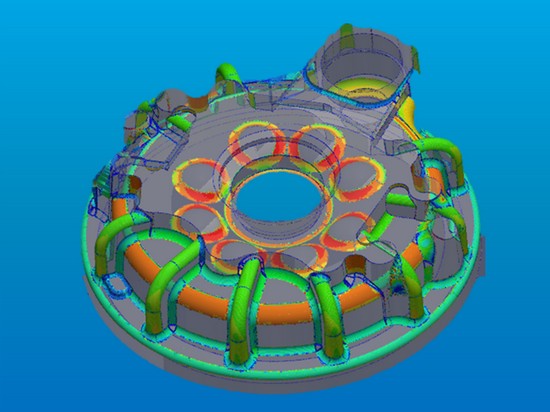
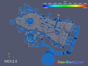
Geo‑Designer utilizes Mass Distribution Index (MDI) analysis to rapidly evaluate the 3D CAD geometry and predict thermal hotspots by analyzing the mass distribution and solidification tendency of the component. The analysis is completed within minutes, allowing designers to make immediate design improvements before moving into die design and detailed casting simulation.

Geo Designer Hotspot - HPDC

1. Optimizing Ingate Location

Understanding hotspot locations helps decide optimum ingate position:

  • Hottest and thickest regions receive sufficient metal
  • Pressure intensification reaches critical zones
  • Better feeding during solidification
  • More balanced filling pattern
Result: Reduced shrinkage & improved casting density
gate design

2. Overflow & Vent Design

Hotspot data guides placement of:

  • Overflows
  • Vents
  • Vacuum channels
  • Critical flow paths
Benefits: Reduced gas porosity, better surface quality
overflow system

3. Cooling System Optimization

Strategic placement of cooling elements:

  • Cooling channels
  • Cooling inserts
  • High thermal conductivity materials
  • Improved heat extraction
Result: Reduced cycle time, increased die life
thermal management

4. Geometry Improvement

Modify component geometry to minimize hotspots:

  • Reduce excessive wall thickness
  • Optimize rib and boss connections
  • Introduce smooth thickness transitions
  • Add cored areas to remove mass
Benefit: Lower component weight, improved quality
design optimization

5. Squeeze Pin & Pressure Control

Determine need for additional feeding assistance:

  • Whether squeeze pins are required
  • Optimum squeeze pin location
  • Area where additional pressure is needed
  • Local pressure application strategy
Result: Improved density in critical structural areas
squeeze pin

6. Reduce Simulation Iterations

Rapid first-level assessment before detailed simulation:

  • Optimize geometry and die concept
  • Identify critical regions early
  • Reduce simulation cycles
  • Faster design decision-making
Result: Lower development cost, shorter time-to-production
simulation ready

Overall Benefits of Early Hotspot Detection in HPDC

  • Identify shrinkage-prone areas before die design begins
  • Optimize ingate location, size, and filling strategy
  • Support overflow, vent, and vacuum system placement
  • Enable effective cooling channel and thermal management design
  • Determine locations requiring squeeze pins or local pressure assistance
  • Improve wall thickness distribution and reduce unnecessary mass
  • Minimize porosity, sink marks, and dimensional defects
  • Reduce expensive die modifications and try-out iterations
  • Improve casting strength, leak tightness, and consistency
  • Reduce development time and achieve First-Time-Right HPDC production
hotspot detection ingate design overflow & vent cooling system geometry optimization squeeze pin
Reduce die modifications by up to 60%
Identifying critical areas at the early product design stage is essential — any change after die manufacturing can result in significant cost, tooling modification, and production delays.

Geo‑Designer Hotspot Detection First‑Time‑Right HPDC

Geo‑Designer provides a fast and intelligent bridge between product design and HPDC die process design. By identifying thermal criticality directly from the CAD model within minutes, engineers can optimize geometry, ingate concepts, cooling strategies, and die design long before expensive tooling and detailed simulation activities begin.

This rapid analysis enables foundries to achieve higher quality castings, fewer trials, improved yield, lower costs, and faster time-to-market.

The first step toward First‑Time‑Right HPDC production

Other Geo-Designer Features

Wall Thickness Analysis
Geo-Designer
Wall Thickness Analysis
Wall thickness has a direct influence on metal flow, cooling behavior, solidification, mechanical properties, and overall casting quality. Geo-Designer performs complete 3D wall thickness evaluation.
  • Analysis Capabilities:
  • ▹ Identify thick and thin regions
  • ▹ Detect abrupt thickness transitions
  • ▹ Highlight areas with uneven cooling
  • ▹ Support lightweight design
  • Benefits:
  • ▹ Improved casting quality
  • ▹ Reduced shrinkage and distortion
  • ▹ Lower component weight
  • ▹ Better process stability
📏 Thickness 🔥 Hotspots ⚖️ Lightweight 📊 Uniformity
Ejection Force Calculation
Geo-Designer
Ejection Analysis
Geo-Designer evaluates the interaction between the casting and the mold during part ejection to ensure smooth component release and minimize deformation.
  • Analysis Capabilities:
  • ▹ Analysis of draft conditions
  • ▹ Prediction of ejection resistance
  • ▹ Identification of areas requiring additional ejector support
  • ▹ Assistance in ejector pin positioning
  • Benefits:
  • ▹ Smooth component release
  • ▹ Reduced risk of deformation
  • ▹ Lower die wear
  • ▹ Improved production reliability
⬆️ Ejection 📌 Ejector pins 🔧 Draft ✅ Reliability
Slider Zone Detection
Geo-Designer
Slider Zone Detection
Complex casting geometries often contain features that cannot be released using the main mold opening direction. Geo-Designer automatically detects areas requiring sliders, side cores, and moving mold elements.
  • Analysis Capabilities:
  • ▹ Automatic slider zone detection
  • ▹ Side core requirement identification
  • ▹ Moving mold element detection
  • ▹ Slider direction optimization
  • Benefits:
  • ▹ Early estimation of tooling complexity
  • ▹ Reduction of unnecessary sliders
  • ▹ Lower tooling cost
  • ▹ Faster mold design
🔧 Sliders 📦 Side cores 💲 Tooling cost ⚡ Fast design
Slider Zone Detection
Geo-Designer
Undercut Analysis
Undercut regions prevent direct part removal from the mold and increase tooling complexity. Geo-Designer identifies internal and external undercuts and areas requiring special tooling solutions.
  • Analysis Capabilities:
  • ▹ Internal and external undercut detection
  • ▹ Direction of undercut formation
  • ▹ Areas requiring special tooling solutions
  • ▹ Undercut severity assessment
  • Benefits:
  • ▹ Avoid expensive mold modifications
  • ▹ Improve mold opening strategy
  • ▹ Reduce manufacturing risks
  • ▹ Optimize tooling complexity
🔄 Undercut 🔧 Tooling 💰 Cost reduction ⚠️ Risk reduction
Draft Angle
Geo-Designer
Draft Angle Checking
Proper draft angle is essential for smooth removal of cast parts from the mold or die. Geo-Designer analyzes the complete model and highlights insufficient or negative draft areas.
  • Analysis Capabilities:
  • ▹ Insufficient draft area detection
  • ▹ Negative draft region identification
  • ▹ Areas requiring geometry modification
  • ▹ Draft angle optimization
  • Benefits:
  • ▹ Easier part release
  • ▹ Reduced surface damage
  • ▹ Increased die life
  • ▹ Improved production efficiency
📐 Draft 🔧 Geometry ✅ Release 🏭 Efficiency
Radius Checking
Geo-Designer
Radius Checking
Sharp corners create stress concentration and uneven solidification. Geo-Designer checks fillet and corner radii, sharp transitions, and areas requiring smoother geometry.
  • Analysis Capabilities:
  • ▹ Fillet and corner radii checking
  • ▹ Sharp transition detection
  • ▹ Areas requiring smoother geometry
  • ▹ Radius optimization
  • Benefits:
  • ▹ Better metal flow
  • ▹ Reduced stress concentration
  • ▹ Improved casting strength
  • ▹ Lower defect probability
🔵 Fillets 📐 Corners 💪 Strength ✅ Quality
Core Model Extraction
Geo-Designer
Core Extraction & Core Design Support
Complex internal passages require accurate core design. Geo-Designer provides automatic core extraction, core geometry generation, core print identification, and core design optimization.
  • Analysis Capabilities:
  • ▹ Automatic core extraction
  • ▹ Core geometry generation
  • ▹ Core print identification and support
  • ▹ Core design optimization
  • Benefits:
  • ▹ Reduced manual CAD work
  • ▹ Faster tooling development
  • ▹ Improved core accuracy
  • ▹ Reduced design errors
🏗️ Core 📐 Geometry ⚡ Automation ✅ Accuracy
Partling Line
Geo-Designer
Parting Line & Mold Design Support
Selecting the correct parting direction and parting line is critical for successful tooling. Geo-Designer helps engineers determine optimum mold opening direction and evaluate parting complexity.
  • Analysis Capabilities:
  • ▹ Determine optimum mold opening direction
  • ▹ Analyze projected area
  • ▹ Evaluate parting complexity
  • ▹ Support cavity and die layout
  • Benefits:
  • ▹ Simplified tooling
  • ▹ Reduced manufacturing cost
  • ▹ Improved mold performance
  • ▹ Faster mold design
➖ Parting 🔧 Mold design 💰 Cost reduction ⚡ Fast design
Yield Optimization
Geo-Designer
Design Optimization
Geo-Designer allows engineers to improve the casting geometry before manufacturing. Optimization includes wall thickness modification, rib and boss optimization, material reduction, and weight optimization.
  • Optimization Areas:
  • ▹ Wall thickness modification
  • ▹ Rib and boss optimization
  • ▹ Material reduction
  • ▹ Weight optimization
  • ▹ Improvement of feeding behavior
  • Benefits:
  • ▹ Lightweight products
  • ▹ Lower material consumption
  • ▹ Improved manufacturability
  • ▹ Reduced production cost
🎯 Optimization ⚖️ Lightweight 💰 Cost reduction ✅ Manufacturability
Geometry Information
Geo-Designer
Geometric Analysis Information
Geo-Designer provides comprehensive manufacturing information directly from the CAD model for faster process planning and improved communication between design and manufacturing teams.
  • Analysis Information:
  • ▹ Component mass
  • ▹ Volume calculation
  • ▹ Surface area
  • ▹ Projected area
  • ▹ Thickness distribution
  • ▹ Mass distribution index (MDI)
  • ▹ Cooling tendency
  • Benefits:
  • ▹ Faster process planning
  • ▹ Improved quotation accuracy
  • ▹ Better communication between design and manufacturing teams
  • ▹ Data-driven decision making
📊 Mass 📐 Volume 📏 MDI 📈 Data

Geo-Designer Workflow Gravity Casting

Six steps from CAD import to optimized feeding design

Geo Designer Capabilities
Step 1

Import 3D CAD Geometry

Import the casting component using standard CAD formats:

  • STEP
  • IGES
  • STL

Accepts complex geometries directly from design systems.

CAD import
Geo Designer Capabilities
Step 2

Automatic Meshing & Preparation

Geo-Designer automatically creates the analysis mesh within approximately one minute regardless of model complexity.

Eliminates time-consuming preprocessing and allows engineers to immediately begin DFM evaluation.

mesh ready
Geo Designer Capabilities
Step 3

Perform MDI Hotspot Analysis

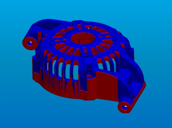
The software evaluates:

  • Wall thickness distribution
  • Mass concentration
  • Thermal hotspot locations
  • Regions that will solidify last

These areas represent potential shrinkage defect locations.

MDI analysis
Geo Designer Capabilities
Step 4

Evaluate Feeding Requirement

Engineers study the hotspot locations and determine:

  • Whether a riser is required
  • Appropriate riser placement
  • Need for sleeves or chills
  • Possible geometry modifications
feeding strategy
Geo Designer Capabilities
Step 5

Create Riser and Feeding Design

Using built-in design functions, the engineer creates:

  • Risers
  • Feeders
  • Sleeves
  • Chills

The feeding system is integrated directly with the CAD geometry.

design integration
Geo Designer Capabilities
Step 6

Verify and Optimize the Design

MDI analysis is repeated to confirm that:

  • Critical hotspot has moved from casting to riser
  • Feeding is sufficient
  • Riser size is not excessive
  • Casting yield is optimized

Final optimized geometry can be exported to CAD or transferred for detailed casting simulation.

verified & optimized

Who Should Use Geo‑Designer? Role‑based Applications

From product design to sales — empower every team with manufacturability insights

Product Design Engineers

  • Validate product designs for manufacturability
  • Reduce weight while maintaining performance
  • Improve wall thickness distribution
  • Eliminate potential casting defects before tooling
design validation

Foundry Process Engineers

  • Analyze casting feasibility quickly
  • Design and optimize risers, sleeves, and feeding systems
  • Improve casting yield
  • Reduce shop-floor trials
process optimization

Tool and Mold Designers

  • Identify parting directions
  • Detect sliders and undercuts
  • Analyze draft angles
  • Simplify mold construction
mold design

Manufacturing Engineers

  • Improve process planning
  • Understand critical regions
  • Reduce production problems
  • Increase manufacturing efficiency
production efficiency

Sales and Quotation Teams

  • Quickly assess manufacturing complexity
  • Estimate tooling difficulty
  • Calculate product mass and projected area
  • Provide faster and more accurate quotations
  • Improve communication with customers using visual DFM reports
quoting & sales

Advanced Visualization & CAD Integration DFM Tools

Powerful visualization for better understanding of casting geometry & challenges

Visualization Features

  • 3D Iso-surface display similar to X-ray and CT scanning
  • Adjustable transparency for internal feature inspection
  • Multiple section and clipping views
  • Dynamic point-based information display
  • Clear color maps for thickness and hotspot distribution

CAD Integration

  • Standalone software platform
  • Direct import of STEP, IGES, and STL formats
  • Built-in geometry modification tools
  • Boolean operations at mesh level
  • Export optimized designs back to CAD systems
  • Flexible report generation and VRML output

Casting Processes Supported Versatile

Suitable for virtually all casting processes

Its process-independent geometric analysis makes Geo‑Designer an ideal DFM solution across the complete casting industry.

High Pressure Die Casting (HPDC)
Gravity Die Casting
Low Pressure Die Casting (LPDC)
Sand Casting
Investment Casting
Centrifugal Casting
Permanent Mold Casting
And more...

Geo‑Designer – The First Step Toward First‑Time‑Right Casting

Geo‑Designer bridges the gap between product design and casting manufacturing by providing rapid, intelligent DFM analysis directly from 3D CAD geometry. Through fast hotspot detection, wall thickness evaluation, gating and feeding optimization, and tooling feasibility analysis, engineers can identify and eliminate manufacturing risks before production begins.

When combined with detailed casting flow, solidification, and stress simulation, Geo‑Designer becomes the first and most critical step in a complete digital casting engineering workflow — enabling foundries to achieve higher quality castings, fewer trials, improved yield, lower costs, and faster time‑to‑market.

The first step toward First‑Time‑Right

Rapid Hotspot Analysis vs Detailed Casting Simulation

Fast DFM evaluation vs complete physical process analysis

Geo‑Designer provides a fast DFM evaluation based on geometry and mass distribution, while detailed casting simulation provides a complete physical analysis of the manufacturing process.

Geo‑Designer Rapid Analysis Detailed Casting Simulation
Analysis completed within minutes Requires longer computational time
Uses MDI to identify thermal hotspots Uses numerical simulation of fluid flow and solidification
Requires only CAD geometry Requires complete process parameters
Best suited for early product design Best suited for process validation and optimization
Determines riser concept and feeding strategy Predicts actual shrinkage porosity and defect formation
Supports quick design iterations Provides detailed temperature, velocity, and solidification results
Reduces unnecessary simulation iterations Optimizes final manufacturing conditions

Rapid Hot-Spot Analysis vs Detailed Shrinkage Prediction

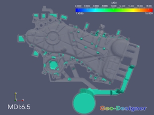
Geo-Designer provides immediate MDI results in minutes, while Cast-Designer delivers comprehensive shrinkage porosity analysis through detailed flow and solidification simulation.

Geo-Designer MDI Analysis 1
Geo-Designer

MDI Hot-Spot Analysis

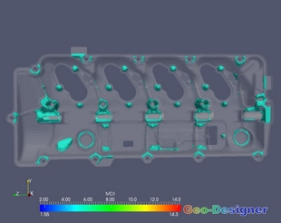
Identifies potential defect areas based on geometric characteristics and mass distribution.

Geo-Designer MDI Analysis 2
Geo-Designer

Quick Design Evaluation

Provides immediate feedback on design quality in 2-3 minutes.

Cast-Designer Shrinkage Analysis
Cast-Designer

Shrinkage Porosity Analysis

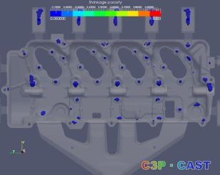
Detailed simulation showing actual shrinkage porosity locations after 2-3 hours of analysis.

2-3 Minutes vs 2-3 Hours Analysis Time
Geo-Designer MDI Analysis 3
Geo-Designer

Early Stage Detection

Flags potential problem areas before detailed simulation begins.

Geo-Designer MDI Analysis 4
Geo-Designer

Design Guidance

Suggests modifications to improve casting quality.

Cast-Designer Shrinkage Analysis 2
Cast-Designer

Validation Simulation

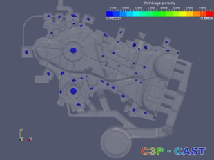
Confirms final design performance with precise porosity prediction.

NESTech Services and Products

Why Choose NESTech as your CAD CAE Partner?

+ Drawings Created
+ Simulations done
+ Team Members
+ Years of Experience
Experience Icon

RICH EXPERIENCE

We bring 25+ years of rich experience to every project, ensuring exceptional results and unparalleled reliability.

Delivery Icon

ON-TIME DELIVERY

With meticulous planning, streamlined processes, and a dedicated team, we ensure that every project is completed promptly and efficiently

Teamwork Icon

EXCELLENT COLLABORATION

We foster a culture of teamwork, communication, and mutual respect, ensuring that every project benefits from the diverse perspectives and expertise of our team members.

Cost Icon

COST EFFECTIVENESS

With a multitude of projects Completed and catering to various industries, we have demonstrated excellent business results at lower cost with our domain expertise.

Some of the Cast-Designer Software Customers